I wanted to build 2 identical Minis for Gilles to try them in bi-amping mode... well, that won't happen.
When I purchased the parts ages ago to build my first Mini, I knew there was a mistake in the BOM (C4 & C5 showing quantity 3 instead of 4).
I knew it... and I sadly completely forgot about it, stupid me. Confident, I just followed the shop's link to the excellent build guide which led me to the Mini's updated BOM (V1.1)... which I assumed would be correct(ed). I expect most beginners just to do the same and not to read all the post's pages. Well, the updated BOM sadly still displays the same mistake: quantity 3 instead of 4.
Too late for me (I just put last week 2 orders at Mouser and Digi and won't just order 1 single cap), but I would say it might be useful to have a corrected BOM V1.2 for future builders. Just recommending, not commanding of course, and again my mistake to go too quickly on such a simple build.
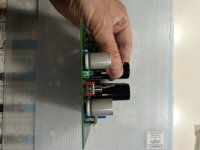
As of me, I decided to take whatever I had handy. I had just a couple of hours at lunch time to assemble the passive section of the Mini. So I went for C4 = 3000uF / 35V instead of 1000uF/25V. It just fits (no contact etc.)
I don't expect any sonic change / benefits due to the uprated RC filtering function, nor ESR change (due to the 6.8k R in front). Nor do I expect anything else to go seriously wrong or this change to create a functional problem... BUT please let me know if I am wrong.
I do believe the only change will be that the time constant at start up will be 3x higher, That is from 7s to 21s, so a slow start up... and that's it hopefully.
PLEASE tell me if I am mistaken, the caps are in place and this Mini isn't in fact for me but for a friend, so it will go out and needs to be tip top... it is even better built than my own LOL
Many thanks
Claude
When I purchased the parts ages ago to build my first Mini, I knew there was a mistake in the BOM (C4 & C5 showing quantity 3 instead of 4).
I knew it... and I sadly completely forgot about it, stupid me. Confident, I just followed the shop's link to the excellent build guide which led me to the Mini's updated BOM (V1.1)... which I assumed would be correct(ed). I expect most beginners just to do the same and not to read all the post's pages. Well, the updated BOM sadly still displays the same mistake: quantity 3 instead of 4.
Too late for me (I just put last week 2 orders at Mouser and Digi and won't just order 1 single cap), but I would say it might be useful to have a corrected BOM V1.2 for future builders. Just recommending, not commanding of course, and again my mistake to go too quickly on such a simple build.
As of me, I decided to take whatever I had handy. I had just a couple of hours at lunch time to assemble the passive section of the Mini. So I went for C4 = 3000uF / 35V instead of 1000uF/25V. It just fits (no contact etc.)
I don't expect any sonic change / benefits due to the uprated RC filtering function, nor ESR change (due to the 6.8k R in front). Nor do I expect anything else to go seriously wrong or this change to create a functional problem... BUT please let me know if I am wrong.
I do believe the only change will be that the time constant at start up will be 3x higher, That is from 7s to 21s, so a slow start up... and that's it hopefully.
PLEASE tell me if I am mistaken, the caps are in place and this Mini isn't in fact for me but for a friend, so it will go out and needs to be tip top... it is even better built than my own LOL
Many thanks
Claude
Attachments
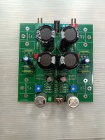
I don’t have an answer for the circuit details, but if you have your own Mini, you can swap out the 1000 uF caps from it to the Mini for your friend, and see how things go with the 3K caps in your amp. Just a logistical suggestion. Certainly, wait for more wise circuit advice before going into desoldering. If the 3K change is not a problem, no need to risk lifted tracks or PCB problems. The silver caps look cool. 😎
Last edited:
Ahhh, thanks von Ah,
Nice but that's even more work, my build is finished LOL... I was just hoping for confirmation that all is OK trippling the C4 value
Nice but that's even more work, my build is finished LOL... I was just hoping for confirmation that all is OK trippling the C4 value
Oh bloody hell! Mistook C4 and C5 in the schematic... when things start to go wrong and you are working too fast... things get even worst LOL
So... Ignore my comments re time constant and RC etc.
I better leave the experts here comment than me guessing...
QUESTION
Is there any problem me using 3000uF at C4 instead of 1000uF???
I guess no but have no clue what effect that cap has other than decoupling... does this affect sound (impact on feedback resistors perhaps?)... or even worst re function (oscillations or whatever)?
Need expert advice here, please
Many thanks in advance
Claude


Very simple build, done twice, running after time and Digi losing my old order... Gremlins KNEW IT, LOL!
Hope I can get away with that 3000uF, would be handy
Hope I can get away with that 3000uF, would be handy
I know the BOM was corrected somewhere, but obviously not the one you saw.
I can send you a 1000uF/25V cap for the missing C4, C5 if you're in North America. DM your address to me.
I can send you a 1000uF/25V cap for the missing C4, C5 if you're in North America. DM your address to me.
Oh, that's extremely nice of you, SIR!
"Sadly" I am in Europe, but again thank you very much for your kindness.
Yep, although I built the Mini quite recently, I had purchased one of the very early ones and did my own BOM back then, even upgrading it to Papa's change re resistors / ramp up at start in case of.
But I am building this one for Gilles, latest version, so lazy me to get me started again I simply went to the build guide and followed the link to the BOM, defo a later version than in the initial paper.
TBH, considering my unit, if it is acceptable, I just leave things as they are. If it isn't, well, it is for me "desoldering and trying to find a small electronic shop" - after all, it is a very common value.
IMHO the main bit here would be to update the BOM linked to the build guide so future builders don't get stuck - I guess the Mini is more to get new people started so ne need to stress them LOL
As of me, can anyone confirm if C4 = 3000uF instead of 1000uF is fine?
Many thanks again
Claude
Err... No one to confirm the impact of changing C4?
If Ok that would save my day, otherwise I am likely to spend hours finding a 4th cap...
Argh... maybe the question was more complicated, it is design after all...
Dear Papa... Help please!... If I may ask?
Thanks in advance
Claude
If Ok that would save my day, otherwise I am likely to spend hours finding a 4th cap...
Argh... maybe the question was more complicated, it is design after all...
Dear Papa... Help please!... If I may ask?
Thanks in advance
Claude
When I purchased the parts ages ago to build my first Mini, I knew there was a mistake in the BOM (C4 & C5 showing quantity 3 instead of 4).
I knew it... and I sadly completely forgot about it, stupid me. Confident, I just followed the shop's link to the excellent build guide which led me to the Mini's updated BOM (V1.1)... which I assumed would be correct(ed). I expect most beginners just to do the same and not to read all the post's pages. Well, the updated BOM sadly still displays the same mistake: quantity 3 instead of 4.
I accidentally clicked on this thread instead of a different one but figured since I was going to be ordering parts for one of these I might as well see what the most recent comments were. I'm so glad I did because this made me re-check my BOM before placing my order tonight and sure enough I mistakenly had 3 of this part in my cart instead of 4.
I know the BOM was corrected somewhere, but obviously not the one you saw.
The pdf and xlsx in the first post of this thread, as well as the xlsx linked to from here, all have a quantity of 3 for C4, C5.
Yes sadly, none of the BOM I could find have been corrected on that matter. I should have checked, first time I avoided this silly mistake... and then I forgot about it.
I am glad I could at least save YOU from doing the same mistake! The Mini is a fantastic little amp, you will... hear.
As of me, purchasing "just" one 1000uF cap is PITA... cost as much as the basic kit.
Is there ANYONE who could tell me if carrying on with my "on hand" 3000uF caps" is acceptable or not? I am building it for a friend so want to go safe...
Many thanks in advance for your HELP
Claude
Let me see if I can be useful Claude.
C4 is in the NF network and will determine the LF cut-off:
when C4 is 1000uF F3 is 1.6Hz, when it's 3000uF it's 0.5Hz.
The overall LF cut-off depends on C2 and R7, when R7 is in parallel with the load, either 8 Ohm or 4 Ohm.
So I think with C4 you are safe.
C5 is even easier as it forms a LPF with R4 and both determine how long it takes for the circuit to become operational:
When R4 is 6.8kOhm the time constant is 6.8 seconds (with 1000uF).
Later Mr. Pass changed it to 22kOhm so time constant becomes 22 seconds.
With C5 3000uF the time constant varies between 20 sec and 66 sec, depending on R4.
So if you want to stay with 3000uF maybe consider this.
You might want to go back to 6.8kOhm for R4 to be within 20 sec. of charging C5.
It sounds cumbersome and convoluted but it's not.
This calculator might help:
https://sengpielaudio.com/calculator-RCpad.htm
P.S. Just saw that your C5 is 1000uF so ignore the above about it. Still positive you are safe with C4 @ 3000uF.
Last edited:
Ah, Stanislav, you are making my day!!!
Looking meanwhile on my side, I assumed "somehow" that C4 was indeed determining a low pass Fc re gain "or so", but absolutely glad you confirmed it..., and even better with values and the additional confirmation I should be safe. Many many thanks for that!
When I looked into it I wasn't able to calculate the impact (now thanks to your explanation I will be and additional bonus I learned something!).
My fear was that perhaps it was too low a Fc, too close to DC or whatever, leading to some odd behaviours - especialy when adjusting the bias & Co especialy as there would be no load re speakers when doing that - so from what you kindly wrote I can carry on without fear.
Many many thanks again for taking so much time for a detailled and educative explanation, very much appreciated.
Enjoy music
Claude
A high pass!that C4 was indeed determining a low pass Fc
Yes absolutely, sorry, meant low cut frequency, my bad, typing too fast during brakes LOL!
Thanks for correcting me!
Claude
Thanks for correcting me!
Claude
To be precise (and to confuse the enemy): it is a high pass in the feedback path, reducing frequencies over 0,5Hz. In this sense, the term "low pass" is not completely false 🙂
Second Mini alive and kicking since a couple of hours.
Special thanks to Stanislav and WBS, who encouraged me to carry on with the "wrong" C4 caps, and Franz for correcting me. Nothing blew up so far, all OK guys ;-)
It is trully a remarkable unit, and consistant: this very late kit sounds very similar (perhaps even identical once ran-in) to my first batch kit.
Two very general remarks for future builders:
1- I believe correcting the BOM on the number of parts required for C4 & C5 would be a good thing. Eg from 3 to 4.
2- Today's kit require four 2k trip pots instead of the initial 1k ones. It makes adjusting twice as sensitive. No prob, you eventualy get there precisely despite the 'play' once you learned how to use the second trim pot for fine adjustements... but it takes twice the time. More an issue for perfectionists, or non patient /non experiment builders. These might want to consider multiturns alternatives.
Other than that, very straight forward, very robust, very easy and quick to assemble, non expensive and fabulous sound, so don't hesitate, this is tremendous VFM.
Claude
I'm glad you were able to sort everything out, and that you are now enjoying the result.
I'll talk with management to see if we can make the changes to the BOM that is posted.
I'll talk with management to see if we can make the changes to the BOM that is posted.
For multiturns, the 2K ohm version of either the Bourns PV36Y or 3296Y will work directly. The 3296W will work if you bend the center pin over and reform it to match the PCB layout. Just be sure to match the 3386P pinout numbers shown in the data sheets. If you bend it the wrong way the pot will work backwards for setting the levels. And if all other availability fails, you can use the 3362P 1/4" smaller pots but those are internally wired reverse of the 3386P and will work backwards. You can also search for equivalents from TT Electronics. The CT-6EP series of single turn 6mm square pots from Nidec (also backwards) are very inexpensive.
- Home
- Amplifiers
- Pass Labs
- DIY ACA mini