Hi again,
Yep, big RCAs might be a problem, that's what I guessed on the pix. But you know it and thankfully it isn't a prob at yours, so all fine!
And Yes, 20ga, is IMHO fine aswell.
I am looking into more flexible options probably in 18ga, but that's just because they come more handy this side of the Atlantic.
Re max current, just as a side note really... I rather calculated P = RI2, with 8W into 4R (Papa's paper), so 1,4A... decided to go safe with gauge handling 1.7 to 2A peaks. But that's overdoing it as eventhough the Mini could possibly squeeze 1 more W into 3R (??), no music signal is going to drive this unit to max power all the time (not to mention no DC signal etc.)
All good then, thanks!
Claude
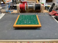
Some chiseling to make sure the 2 recesses for the now 4 additional caps are flat and nice... although no one is ever going to lift the board, so more for clearances issues and me wasting time polishing my toy LOL
Of course visible parts will see fine sand paper and verneer, but that's for later.
Pix for those needing hints on where to put the recesses if using the same bypass caps as I do... don't ask me where the tiny white feather on top of the pix / the wood frame came from when the pix was taken!
Of course visible parts will see fine sand paper and verneer, but that's for later.
Pix for those needing hints on where to put the recesses if using the same bypass caps as I do... don't ask me where the tiny white feather on top of the pix / the wood frame came from when the pix was taken!
Attachments

@avdesignguru
20ga is listed @1.5A for power transmission but the chassis wiring ampacity rating is 11A. All good.
20ga is listed @1.5A for power transmission but the chassis wiring ampacity rating is 11A. All good.
The NEC is a product of the National Fire Protection Association (NFPA) and uses a huge safety factor as one might imagine.
Different ampacity tables apply to differing applications. A 14ga wire is the required min size behind a 15A breaker but the tables that pertain to chassis/fixture (free air) wiring show 18ga 90C rated cable @ 18A within a 30C environment... above that derating factors come into play.
Different ampacity tables apply to differing applications. A 14ga wire is the required min size behind a 15A breaker but the tables that pertain to chassis/fixture (free air) wiring show 18ga 90C rated cable @ 18A within a 30C environment... above that derating factors come into play.
Birdbox:
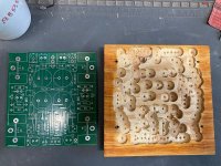
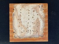
I thought I'd put together some pics of a simplified base design. No binding posts or recessed PCB but it's easy. No router required, just a saw (preferably table saw but a hand power saw will work if you clamp a guide bar in place) and a drill (preferably a drill press). The only "special" tool I used is a forstner bit but even regular bits could be used, just more difficult to control the depth. I used a half inch but other sizes should work fine. Something like this: https://www.amazon.com/Irwin-Tools-1966896-Drilling-Forstner/dp/B01JIKB7IQ You could probably even skip the drill and just chisel everything out by hand, as long as you go deep enough to clear the solder pads after the leads are trimmed.
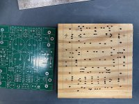
This design works best if you lay out the base before you stuff or build the PCB since it gets used as a marking guide. Start by cutting a 5-1/2" square of 3/4" plywood. It helps to use something with a nice finish but even regular AC will work if it is reasonably void free. This base was made with a scrap piece of standard 5-ply ACX. Then bevel 3 sides at 45 degrees, 2 plys down from the top. Lay the PCB on top, centered left-to-right, with the rear edge flush with the rear of the base and lightly pencil in the outline, then mark all the holes. I used a 0.5mm mechanical pencil and followed up with a sharpie marker.
I set my drill press stop for about a 1/4" depth of drilling and drilled out all the pad areas. Be sure to stay at least 1/8" back from the PCB edge lines and the mounting hole locations. There's only one pad along the front side of the board that is really close to the edge. You can always go back after the PCB is built and remove any wood that interferes with it setting flush.
Then it's just sand, stain and finish the base and add either stick on or screw down feet of your choice. Be sure to drill pilot holes for all of the mounting screws to avoid splitting the plywood.
I thought I'd put together some pics of a simplified base design. No binding posts or recessed PCB but it's easy. No router required, just a saw (preferably table saw but a hand power saw will work if you clamp a guide bar in place) and a drill (preferably a drill press). The only "special" tool I used is a forstner bit but even regular bits could be used, just more difficult to control the depth. I used a half inch but other sizes should work fine. Something like this: https://www.amazon.com/Irwin-Tools-1966896-Drilling-Forstner/dp/B01JIKB7IQ You could probably even skip the drill and just chisel everything out by hand, as long as you go deep enough to clear the solder pads after the leads are trimmed.
This design works best if you lay out the base before you stuff or build the PCB since it gets used as a marking guide. Start by cutting a 5-1/2" square of 3/4" plywood. It helps to use something with a nice finish but even regular AC will work if it is reasonably void free. This base was made with a scrap piece of standard 5-ply ACX. Then bevel 3 sides at 45 degrees, 2 plys down from the top. Lay the PCB on top, centered left-to-right, with the rear edge flush with the rear of the base and lightly pencil in the outline, then mark all the holes. I used a 0.5mm mechanical pencil and followed up with a sharpie marker.
I set my drill press stop for about a 1/4" depth of drilling and drilled out all the pad areas. Be sure to stay at least 1/8" back from the PCB edge lines and the mounting hole locations. There's only one pad along the front side of the board that is really close to the edge. You can always go back after the PCB is built and remove any wood that interferes with it setting flush.
Then it's just sand, stain and finish the base and add either stick on or screw down feet of your choice. Be sure to drill pilot holes for all of the mounting screws to avoid splitting the plywood.
Attachments
I am pretty sure someone did what follows before, be it for this projetc or another....
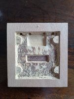
Of course it ends up being higher in dimensions and probably less elegant re woodworking, but for those wanting a very quick and easy solution 2 thin boards can be used.
Cut both boards cut to the desired outside dimensions.
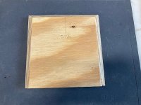
The first board remains untouched except for 4 little holes for stand offs with the wanted height.
The second board is completely cut inside so just an empty frame remains. It is cut to the dimensions of the Mini board so it can slide into it.
Glue the first board with the second, stacked, the first being the bottom section, the second one the top section.
Put the Mini on the stand offs, fits inside your frame, no one knows what clearance / hole is underneat.
Oh, make sure there is some space under the board so you can try out the bypass cap tweaks I posted recently... anyone?
Have fun guys!
Claude (with brush and verneer)
Of course it ends up being higher in dimensions and probably less elegant re woodworking, but for those wanting a very quick and easy solution 2 thin boards can be used.
Cut both boards cut to the desired outside dimensions.
The first board remains untouched except for 4 little holes for stand offs with the wanted height.
The second board is completely cut inside so just an empty frame remains. It is cut to the dimensions of the Mini board so it can slide into it.
Glue the first board with the second, stacked, the first being the bottom section, the second one the top section.
Put the Mini on the stand offs, fits inside your frame, no one knows what clearance / hole is underneat.
Oh, make sure there is some space under the board so you can try out the bypass cap tweaks I posted recently... anyone?
Have fun guys!
Claude (with brush and verneer)
LOL!
Varnish of course
Wouldn't mind a real Vermeer at home though, promise I wouldn't tweak it LOL!
Varnish of course
Wouldn't mind a real Vermeer at home though, promise I wouldn't tweak it LOL!
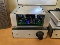
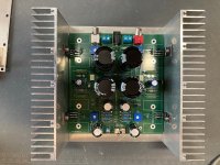
And here's a low profile Mini, made with some 150 x 60 x 25mm heat sinks and some scrap 0.0625" aluminum plate I had laying around. Output device insulators are thin Chinese silicon pads with shoulder washers. The transistor bodies and sinks run a good 5 - 7 deg C cooler than my stock Mini using the same VB at 0.32 - 0.33 V. The surprise was the top cover plate running warm at 48 deg C. maybe a bit worry some with it only 2 - 3mm above the top of the big PS caps as they are getting cooked a little bit.
Attachments
Looks great.
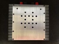
Drill some holes in both the top and bottom plates to assist ventilation. Then you can crank up the bias higher.
Drill some holes in both the top and bottom plates to assist ventilation. Then you can crank up the bias higher.
I'm not sure I want higher bias. Critical listening point for me was when I went from 0.31V to 0.325V. Nirvana.
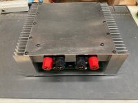
Actually the top and bottom plates are sucking a fair amount of heat by conduction off the main sinks. More the top than the bottom. Front and rear of chassis are wide open but that doesn't seem to help much 😡
I did drill some vents above the PS caps so they will run a bit cooler at their top ends. Heat kills electrolytics. In that way, Papa's original design is better. Even with the black tower sinks blasting away at 60 deg C the heat is mostly going straight up.
Attachments
On my way to build my second ACA Mini, ordered on the day the store reopened (essential kit).
Since I will have to order most of the parts, what's the flavour with the lastest kits regarding trim pots requirement?
Is it 1k (as mine which was the first batch)... or 2k now as I have read somewhere here?
I do understand that 2k is compatible with all as it can do 1k, but given the sensitivity of the adjustement I try to go for as low as possible... without going multiturns.
Perhaps the trim pot requirement is even indicated when I receive my parcel, as trim pots have to be in line with the parts sent?
Many thanks for your help
Claude

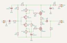
See if you can find International Rectifier Application Note AN-948A. It describes a Class AB power amp using a common Drain output stage.
Answering my own question...
Found in the post N.1 an updated BOM with trim pots being now 2k... so guess I will need those.
If wrong just shout
Claude
Found in the post N.1 an updated BOM with trim pots being now 2k... so guess I will need those.
If wrong just shout
Claude
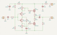
Of course. Corrected!You also need the input JFETs to be common Drain.
Thank you.
But will it actually work like this?
Attachments
Found it, but that's waaaay to complicated for me to mess with.See if you can find International Rectifier Application Note AN-948A.
The ACA Mini is as minimalistic as possible, and still to complicated for me.

- Home
- Amplifiers
- Pass Labs
- DIY ACA mini