So balanced + goes to one input + and balanced - goes to the other input +? Then both + to speaker? What happens to balanced ground?

Take your pick with balanced ground...Input L- or input R-, they all connect anyway.
Balanced ground should still go to ground. As the speakers are driven from both the output Positives, it’s not in the way.
Remember that balanced negative isn’t ground, it’s an inverted signal.
Remember that balanced negative isn’t ground, it’s an inverted signal.
The "balanced" ground goes the the Mini's ground (the ground for both channels is unified on the Mini board).
Decided yesterday to buy and try my hands on a manual wood cutting tool. My first try, No flames, I am neither 6L6 nor Cubicincher...
Although my build isn't done yet (finishing + verneer at least), I thought I might post as I just stopped where people might stop if they aren't modifying their Mini - whereas I am... and that wil include some extra work others won't need.
The idea is to have a non expensive wooden frame (a couple of $) , admittely the time to build it is longer than building the Mini and the tools required more expensive than the kit, but well...
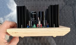
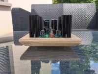
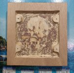
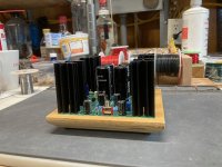
Inspiration is clearly Rega Planar 25 and I wanted the top of the board to sit flush with he top of the frame.
I liked also the look of different lyers in the wood, but that's just me.
Although my build isn't done yet (finishing + verneer at least), I thought I might post as I just stopped where people might stop if they aren't modifying their Mini - whereas I am... and that wil include some extra work others won't need.
The idea is to have a non expensive wooden frame (a couple of $) , admittely the time to build it is longer than building the Mini and the tools required more expensive than the kit, but well...
Inspiration is clearly Rega Planar 25 and I wanted the top of the board to sit flush with he top of the frame.
I liked also the look of different lyers in the wood, but that's just me.
Attachments
Now how I did it...
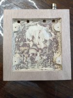
Some pix were taken when work was on progress. Discard for example the extra carving depth in the middle: that's because I am digging deeper there to accomodate my extra bypass caps. But I hope these pix show the principle.
The wood thickness I used was 22mm, that's what I flet was needed to have a frame heavy enough (The Mini easily lifts a leg when big LS cables are connected to it), while also enabling (and that's just me) an easy fit of LS connectors. I found that size also right from an esthetical POV, as the borders a few mm bigger, but again that's just me!
To have the Mini board sitting flush and not on top you can either carve deep everywhere and use washers or stand offs. Or, as I did, leave 4 small aeras of wood around the mounting holes of the Mini. Either way, you want ca 1.5mm depth to make sure the top of the Mini board is recessed / sits flush with the frame. You could go for more, and have the board inside the frame, but beware that the RCA connectors are then likely to be too close to the frame for comfort (big connectors).
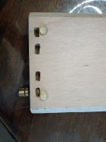
Additional to the mentioned 1 to 2mm, you need to carve to accomodate your soldering work under the Mini board. Anything between 4 and 6 mm should be enough, but more can't harm of course, depending on your frame thickness.
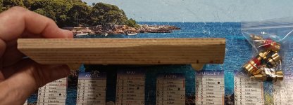
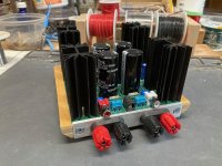
3 sides are partialy chamfered. That's just because I wanted to use my new tool and also because I like it that way.
Important if like me, you wish to fit proper LS terminals is you leave the backside (where the connectors are) flat / not chamfered. Space isn't huge and you better have any additional binding posts sitting horizontal...
And I already went to far as we are talking additional parts. So I stop posting here for now, whereas I will keep carving in the middle to accomodate extra underboard caps. Hmm, while at it might also try bypasscaps in the signal path (on the big caps), never say never
Enjoy your WE very much
Claude
Some pix were taken when work was on progress. Discard for example the extra carving depth in the middle: that's because I am digging deeper there to accomodate my extra bypass caps. But I hope these pix show the principle.
The wood thickness I used was 22mm, that's what I flet was needed to have a frame heavy enough (The Mini easily lifts a leg when big LS cables are connected to it), while also enabling (and that's just me) an easy fit of LS connectors. I found that size also right from an esthetical POV, as the borders a few mm bigger, but again that's just me!
To have the Mini board sitting flush and not on top you can either carve deep everywhere and use washers or stand offs. Or, as I did, leave 4 small aeras of wood around the mounting holes of the Mini. Either way, you want ca 1.5mm depth to make sure the top of the Mini board is recessed / sits flush with the frame. You could go for more, and have the board inside the frame, but beware that the RCA connectors are then likely to be too close to the frame for comfort (big connectors).
Additional to the mentioned 1 to 2mm, you need to carve to accomodate your soldering work under the Mini board. Anything between 4 and 6 mm should be enough, but more can't harm of course, depending on your frame thickness.
3 sides are partialy chamfered. That's just because I wanted to use my new tool and also because I like it that way.
Important if like me, you wish to fit proper LS terminals is you leave the backside (where the connectors are) flat / not chamfered. Space isn't huge and you better have any additional binding posts sitting horizontal...
And I already went to far as we are talking additional parts. So I stop posting here for now, whereas I will keep carving in the middle to accomodate extra underboard caps. Hmm, while at it might also try bypasscaps in the signal path (on the big caps), never say never
Enjoy your WE very much
Claude
Attachments
That looks fantastic! Very good indeed. 🙂 🙂 I had a Planar25 for years and your chamfer is very reminiscent.
My woodworking skills are akin to a 9yr old child who has access to rusty, dull tools. It’s nice to see even simple successes. I’m not on the list of people who can make nice things…

My woodworking skills are akin to a 9yr old child who has access to rusty, dull tools. It’s nice to see even simple successes. I’m not on the list of people who can make nice things…
Nah... not sure we will agree on that ;-)
But thanks for your kind post, Jim!
I have been to the Bourget Air and Space Museum with my young son last month... amazing to see the beautiful details of century old "flying machines" made of wood and cloth! Not far away from ours, should you fancy it...
Have a nice WE and thanks for all your kindness
Claude
I like the "floating island" aesthetic.Decided yesterday to buy and try my hands on a manual wood cutting tool. ...
Kind regards,
Drew
Anyone know what genre of music Nelson Pass was listening to when he came up with this? Just a curiosity based on my own experience with it so far.
(Hope to make the pre-amp soon, just needing to spread my spending out.)
(Hope to make the pre-amp soon, just needing to spread my spending out.)
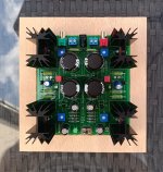
ClaudeG - I liked your plinth design so much I decided to copy it (with a change to the binding post mounting). Unfortunately, I didn't have any 13 ply baltic birch so I had to make do with 7 ply birch (5 cores and 2 veneers).
Attachments
These wood bases look really good!
I plane to build a few ACA Minis with my brothers next week. How are you guys cutting the wood for these wonderful bases? Hand router, CNC, other? Inquiring minds want to know.
I plane to build a few ACA Minis with my brothers next week. How are you guys cutting the wood for these wonderful bases? Hand router, CNC, other? Inquiring minds want to know.
The process I used does require some woodworking skills but if you are careful and go slow, especially when carving with a wood chisel It works out. Plywood can be tricky because the layers want to splinter differently than solid wood.
The basic wood piece is done with a table saw, a router and a wood chisel, with help at times from a drill press. The rear inset for the aluminum strip was done with many multiple cross cuts using the miter sled on the table saw because I was too lazy to to switch to my dado blade. The top inset for the PCB was first done to the thickness of the PCB by holding the piece up against the saw fence while using some spacer strips to get the distance from the edge correct for the router cut. I used a small lightweight laminate trimming router that I could hold in one hand which saved not having to build a jig or do any clamping. The inside routed corners are squared out with a wood chisel. Then 3/8" in from that step down, I did a deeper rout out for bottom of the board solder pad component lead clearance. Some of the solder pads are closer than that to the edge so I marked those locations and used a drill press with a forstner bit for relief in those spots
Rather than chisel out the spaces for the binding post studs, I clamped the piece vertically in a drill press vise and bored holes into the back end with another forstner bit. The 3/4" X 0.125 aluminum strip was drilled for the binding posts and the holes for the insulated mount were enlarged with a step bit. Since it is very difficult to get the post hole spacing totally exactly .75 inches apart and parallel to the edge, you can cheat a bit by using the next step on the bit to chamfer both sides of each hole a bit. If you're off a bit. you could also oversize the 1/2" holes using a 33/64" or maybe even a 17/32" bit but the centering plastic extrusions on my binding posts were so shallow the chamfer trick worked.
The whole thing took maybe an hour or so to do. Wood finish was a quick sand with a sanding block, some alcohol-based aniline dye, which dries almost immediately and some finishing wax.
Hi Avdesignguru,
Whaou, well done!
Glad I could bring some inspiration, especialy given your name... probably the first time I design (well Rega inspiration) something that is worth looking at LOL!
Well done, and yes your backplate makes it much easier than what I did - I mainly wanted to train with new tools and pure handworks (hence everything isn't perfect). The Mini is for friends to get a "Pass taste", not even for my own use. OK, OK, it is so cute and well sounding I couldn't resist anyway! Oh, and for other buildrs, your backplate also enables to use a thinner woodplate while having the binding posts fitting, so all good.
It is probably lighter though, also smaller on the edges - esthetic aside, I found additional weight was good to avoid the Mini lifting with heavy cables, but then there are ways around that and I, anyway... err, I am drilling recesses to add bypass caps LOL
Just 2 points:
Well done again and also thanks for your very detailled post explaining how you did it: I bet it will trigger more of these designs!
On my side I am experimenting further with bypasses, so keep you chisel at hand in case of ;-)
Have a nice day
Claude
Whaou, well done!
Glad I could bring some inspiration, especialy given your name... probably the first time I design (well Rega inspiration) something that is worth looking at LOL!
Well done, and yes your backplate makes it much easier than what I did - I mainly wanted to train with new tools and pure handworks (hence everything isn't perfect). The Mini is for friends to get a "Pass taste", not even for my own use. OK, OK, it is so cute and well sounding I couldn't resist anyway! Oh, and for other buildrs, your backplate also enables to use a thinner woodplate while having the binding posts fitting, so all good.
It is probably lighter though, also smaller on the edges - esthetic aside, I found additional weight was good to avoid the Mini lifting with heavy cables, but then there are ways around that and I, anyway... err, I am drilling recesses to add bypass caps LOL
Just 2 points:
- are you Ok re clearance between your wooden silver backplate and the RCA connectors to accomodate said connectors? Something I had to consider before getting started with my flush board design, as posted. If not easily fix with a small recess in the wood where the connecors are... no issue, just asking based on the pix
- I guess, as I do, you are connecting the binding posts with a small cable under the board directly to the (underside) welding points of the board's LS terminals. If so, what cable size / gauge did you use? On my side I considered 1.4A to be the max, would have taken anything flexible enough to accomodate 2A... and long enough to flip the board of course.
Well done again and also thanks for your very detailled post explaining how you did it: I bet it will trigger more of these designs!
On my side I am experimenting further with bypasses, so keep you chisel at hand in case of ;-)
Have a nice day
Claude
Hi Birdbow,
The tools I used were just :
Oh, I didn't use a vacuum but did most (the big ones) works in my garage as you will get obviously a bit of wood dust everywhere
For the extra carving I did, which is just me to accomodate additional non standard parts etc., I used a small Dremel.
I hope this helps
The tools I used were just :
- an electric hand saw
- a hand router (for all the inside carving... I had bought one I wanted to train on... Some inside bits had to be done removing part of the body and using it as a big Dremel)
- a hand file
- an electric drill for the binding posts holes
Oh, I didn't use a vacuum but did most (the big ones) works in my garage as you will get obviously a bit of wood dust everywhere
For the extra carving I did, which is just me to accomodate additional non standard parts etc., I used a small Dremel.
I hope this helps
Never say never...
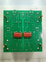
For whatever reason I believed each big output lytics were already bypassed by a small PP cap as that was the case with my VFET. Well, they aren't...
Prefered choice would be to try any PP cap from say 0.1 to... 15uF (the more the better up to a point?) space and budget permitting, but in practice I get usualy limited or remain sensitive (eg. less than 1uF). Here I would opt for any Wima MKP from 0.33 to 1uF, space / footprint being my limit.
While I had a pair of 0.22uF Wima MKP handy, I also found in my drawer a pair of the trully excellent and non expensive Panasonic ECW (tip given by Fab ages ago, I used them a couple of times since). They cost around 1$ each and are quite large 3.3uF, so all good for me. They are a bit bigger in size, but with another orientation than the Wima and the beauty is they just fit perfectly under the output caps! What's not to like?!
Here we go for a listening session, bearing in mind I had little hopes if any... as if they worked that would mean reworking my wooden Mini frame, argh!
Well, I was wrong. To my ears, these bypass caps shone. My notes are:
In terms of magnitude, it made a small but IMHO veryt noticeable change. It has a bit less impact than the previous bypass tweak I suggested (that was PS related) and both in separation have less impact than the additional PS filtering coil... together they bring different things, but I would say at least as much impact overall as the coil in isolation. The big plus being that these tweaks fit so well together and are additive, seldom the was usualy (diminishing returns, sound balance could be altered etc.)
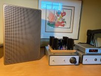
Someone posted I should do pix, so here we go. Bare in mind this is the latest tweak, not the one of the PS caps, which is still ongoing as I hope to get similar results from smaller low ESR caps than the ones I used for that former tweak.
Oh and these are the caps I used here (and I would use again as great VFM)
https://www.mouser.fr/ProductDetail/667-ECW-FD2W335J
I think I am done tweaking this amazing little unit. It sounds trully incredible, I believe close to my VFET re sonic signature, should give it a try one day. So for additional 9$ (Papa will hate me as that's nearly 10% BOM increase) it takes it to my ears to a new level.
Just give it a try: for a few bucks any of the 3 tweaks is doable, and all is easily reversible anyway if you don't like it.
As of me, on my Mini todo list: finalizing the woodframe (more carving for this late tweak), trying the smaller PS bypass caps, trying daisy chaining the coil filters and trying... 2 tweaked ACA Mini in various biamp modes of course!
Enjoy music
Claude
For whatever reason I believed each big output lytics were already bypassed by a small PP cap as that was the case with my VFET. Well, they aren't...
Prefered choice would be to try any PP cap from say 0.1 to... 15uF (the more the better up to a point?) space and budget permitting, but in practice I get usualy limited or remain sensitive (eg. less than 1uF). Here I would opt for any Wima MKP from 0.33 to 1uF, space / footprint being my limit.
While I had a pair of 0.22uF Wima MKP handy, I also found in my drawer a pair of the trully excellent and non expensive Panasonic ECW (tip given by Fab ages ago, I used them a couple of times since). They cost around 1$ each and are quite large 3.3uF, so all good for me. They are a bit bigger in size, but with another orientation than the Wima and the beauty is they just fit perfectly under the output caps! What's not to like?!
Here we go for a listening session, bearing in mind I had little hopes if any... as if they worked that would mean reworking my wooden Mini frame, argh!
Well, I was wrong. To my ears, these bypass caps shone. My notes are:
- fuller / warmer, while not overdoing it
- Better register integration
- More precise, sounds are more realistic
- A bit more dynamic
- No downside at all, just bonus without altering any of the existing quality, just enhencing the Mini
In terms of magnitude, it made a small but IMHO veryt noticeable change. It has a bit less impact than the previous bypass tweak I suggested (that was PS related) and both in separation have less impact than the additional PS filtering coil... together they bring different things, but I would say at least as much impact overall as the coil in isolation. The big plus being that these tweaks fit so well together and are additive, seldom the was usualy (diminishing returns, sound balance could be altered etc.)
Someone posted I should do pix, so here we go. Bare in mind this is the latest tweak, not the one of the PS caps, which is still ongoing as I hope to get similar results from smaller low ESR caps than the ones I used for that former tweak.
Oh and these are the caps I used here (and I would use again as great VFM)
https://www.mouser.fr/ProductDetail/667-ECW-FD2W335J
I think I am done tweaking this amazing little unit. It sounds trully incredible, I believe close to my VFET re sonic signature, should give it a try one day. So for additional 9$ (Papa will hate me as that's nearly 10% BOM increase) it takes it to my ears to a new level.
Just give it a try: for a few bucks any of the 3 tweaks is doable, and all is easily reversible anyway if you don't like it.
As of me, on my Mini todo list: finalizing the woodframe (more carving for this late tweak), trying the smaller PS bypass caps, trying daisy chaining the coil filters and trying... 2 tweaked ACA Mini in various biamp modes of course!
Enjoy music
Claude
Attachments
Ahhh....Having 2 identical amps was a true pleasure when we did Gilles Class D amp... these 2 amps and a set of bespoke LS cables made assessing each tweak sooo easy, switching hin and forth, sometimes blindly... and retaining on both amps the tweaks we liked.
I will have 2 Mini soon, the store has sent the parts already... I consider these little amps as ambassadors of Papa's genius, kind of amps you can easily take to friends to get them a taste of the Maestro...
I will have 2 Mini soon, the store has sent the parts already... I consider these little amps as ambassadors of Papa's genius, kind of amps you can easily take to friends to get them a taste of the Maestro...
ClaudeG:
"Just 2 points:
I used 20ga stranded wire to make the binding post connections to the bottom of the PCB. I'd have to check the PCB traces but I'm guessing that 20ga is heavier than the traces. I believe a 1oz trace would have to be 4mm wide to equal a 20ga wire but I might be wrong. The connecting wires are only about 3 to 4cm long. 20ga is easily good for 1.5A which is 36 watts at 24V. Amplifier is only 5 wpc.
"Just 2 points:
- are you Ok re clearance between your wooden silver backplate and the RCA connectors to accomodate said connectors? Something I had to consider before getting started with my flush board design, as posted. If not easily fix with a small recess in the wood where the connecors are... no issue, just asking based on the pix
- I guess, as I do, you are connecting the binding posts with a small cable under the board directly to the (underside) welding points of the board's LS terminals. If so, what cable size / gauge did you use? On my side I considered 1.4A to be the max, would have taken anything flexible enough to accomodate 2A... and long enough to flip the board of course."
I used 20ga stranded wire to make the binding post connections to the bottom of the PCB. I'd have to check the PCB traces but I'm guessing that 20ga is heavier than the traces. I believe a 1oz trace would have to be 4mm wide to equal a 20ga wire but I might be wrong. The connecting wires are only about 3 to 4cm long. 20ga is easily good for 1.5A which is 36 watts at 24V. Amplifier is only 5 wpc.
- Home
- Amplifiers
- Pass Labs
- DIY ACA mini