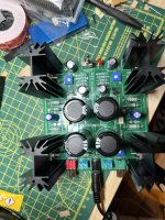
I set Vb on both channels to 0.3V and V0 to 11.5 V
On the left channel (green) heat sinks get hot.
On the right channel (red) heat sinks stay cold.
Heat sinks are connected with screw an a bit of heat paste.
Power indicator led does not pulse (at least I can’t recognise it, but there is no load connected)
On the left channel (green) heat sinks get hot.
On the right channel (red) heat sinks stay cold.
Heat sinks are connected with screw an a bit of heat paste.
Power indicator led does not pulse (at least I can’t recognise it, but there is no load connected)
Attachments

I set Vb on both channels to 0.3V and V0 to 11.5 V
This is important.
If Vb is 0.3 volts on both channels and the value of R8 is correct at 0.75 ohm then the correct current must be flowing. That is just ohms law and its an absolute. 0.3 volts across 0.75 ohm is 0.4 amp and 0.4 amp and 24 volt rails is 9.6 watts and that is shared equally between the two FET's.
That means that the heat dissipated should be the same on both channels. Vout set at 11.5 volts means the two FET's in that channel are equally sharing the power dissipation and should be equally hot.
So if one side really is not get hot then something fundamental is wrong. In that case measure R8 and make sure it is 0.75 ohm and not something like a 7.5 ohm.
I will check all voltages a values tomorrow.
I ordered some special hook clamps today. So I can measure Vb and V0 at the same time while tuning.
I ordered some special hook clamps today. So I can measure Vb and V0 at the same time while tuning.

Gentlemen,
Thank you for your efforts. It seems that only P1 and P2 were not set correctly. Since, at least to the best of my recollection, I played around with the settings for a really long time when I was finishing the amp, I assumed that the settings should be correct.
I have checked all the voltages. checked the resistor values of R8 and everything is correct. I have already tested the amp today. both channels are playing nicely and getting warm (maybe not equaly but significantly warm).
all good. thank you very much and i apologise for any inconvenience. i really do like this community. the level of help one gets here is outstanding.
Cheers
Flo
I have finished my ACA mini but need to do the bias and VO adjustments. This is quite a nifty little amp kit! Very much enjoyed the build.
Off to get an additional multi meter for the adjustments. Will report further..
Off to get an additional multi meter for the adjustments. Will report further..
Got a question. I love the SQ I am getting from my Mini, but I could really use some more gain. I use it for the high frequencies in a bi-amped system with a more sensitive amp for the bass, and I use a buffer preamp with no gain. I have tried a couple of inexpensive step up transformers between the crossover and the Mini, but didn't like what they did to the sound. Right now I am using the line stage of a Threshold FET Two between the crossover and Mini, which works, but I would really like a gain stage in the same box as the Mini. Anyone else have this issue? Anybody try the DIY FE22 with the Mini? What else should I look at?
I have an ACA mini PCB that was generously included with a finished amp I purchased from a member here. I am wondering if I can build a higher output power version by increasing the supply voltage to 30-32v and the bias to about 600mA. I would upgrade the caps to 35v versions and use much bigger heatsinks. I have a couple of about 1degC/watt heatsinks I think would work. I was also wondering if it would make sense to switch to irf540 from irf520 fets The dissipation per device would be about 10W, still well below the 60W maximum for the irf520, but I would appreciate people's opinions
Thanks.
Thanks.
this might answer some of your questions: https://www.diyaudio.com/community/threads/aca-minmax-aca-mini-retrofit-for-aca-chassis.404975/
I went to do the VB and VO adjustments having zeroed ( counter clockwise ) all four trim pots first and i am getting 12 V on both channels VO. Left the mini on for a while and none of the heating sinks were getting warm. Something must be seriously amiss. guess I will have to post some pics....


I'll say on my first build I got two of the MOSFETs swapped. Easy to cross check that. It was no fun desoldering those to fix my issue (brings back desoldering PTSD memories), but the dang thing sounds so amazing it was worth the pain.
Thanks fellas, I'm taking a break and will get back to it in a couple hours. Iirc Ben, the VB was zero. I did go back over the soldering.
Buonasera, mi inserisco in questa discussione perché ho un problema. Ho costruito il mio mini ACA seguendo esattamente la guida 6L6 sulle guide audio fai da te, ho apportato modifiche su V0 (11,47 volt) e VB (0,303 mV) su entrambi i canali, i dissipatori di calore si riscaldano come dovrebbero ma un canale emette rumore distorcente. Non ho possibilità di effettuare altre misurazioni e quindi chiedo cosa potrebbe essere e cosa posso verificare?
grazie Giampiero
grazie Giampiero
Buonasera, mi inserisco in questa discussione perché ho un problema. Ho costruito il mio mini ACA seguendo esattamente la guida 6L6 sulle guide audio fai da te, ho apportato modifiche su V0 (11,47 volt) e VB (0,303 mV) su entrambi i canali, i dissipatori di calore si riscaldano come dovrebbero ma un canale emette rumore distorcente. Non ho possibilità di effettuare altre misurazioni e quindi chiedo cosa potrebbe essere e cosa posso verificare?
grazie Giampiero
 English please.
Good evening, I am entering this discussion because I have a problem. I built my mini ACA exactly following the 6L6 guide on DIY audio guides, made changes on V0 (11.47 volts) and VB (0.303 mV) on both channels, the heatsinks heat up as they should but one channel makes distorting noise. I don't have the possibility to take any other measurements and so I ask what could it be and what can I verify?
thank you Giampiero
- Home
- Amplifiers
- Pass Labs
- DIY ACA mini