modified results
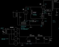
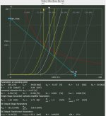
So, I finally got the circuit modified where #45 is running at around 250-260V plate, -50V bias and 34-38mA and #26 at around 150-160V plate, -10.5V bias and 5-6mA (values depending on actual tube-to-tube variations); se attached actual measured values.
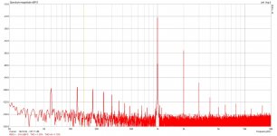
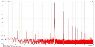
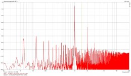
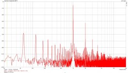
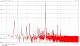
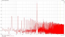
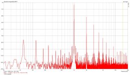
While the amp is sounding really VERY GOOD, I did not really get ANY measurable change in distortion by adjusting this operating points. I am still basically just over 1% THD at 0.1W and just over 4% THD at 1W output. Spectrum is dominated by 2nd order distortion (around -36db at 0.1W; -28db at 1W) while 3rd order is much further down (-74db at 0.1W and -68db at 1W); see attached spectrum for 0.1W and 1W.
I am wondering if this relatively high measured distortion is a problem I should try to solve and, if yes, what would be the best next step to try?
Thanks for any suggestions/opinions!
So, I finally got the circuit modified where #45 is running at around 250-260V plate, -50V bias and 34-38mA and #26 at around 150-160V plate, -10.5V bias and 5-6mA (values depending on actual tube-to-tube variations); se attached actual measured values.
While the amp is sounding really VERY GOOD, I did not really get ANY measurable change in distortion by adjusting this operating points. I am still basically just over 1% THD at 0.1W and just over 4% THD at 1W output. Spectrum is dominated by 2nd order distortion (around -36db at 0.1W; -28db at 1W) while 3rd order is much further down (-74db at 0.1W and -68db at 1W); see attached spectrum for 0.1W and 1W.
I am wondering if this relatively high measured distortion is a problem I should try to solve and, if yes, what would be the best next step to try?
Thanks for any suggestions/opinions!
Attachments
Are you sure distortion isn't coming from the source with that input step-up transformer? Are your actual tubes good enough?
Over 1% at 0.1W is really a lot for a 45 amp in my experience and you are definitively hearing distortion. If you like it that's another matter....
Over 1% at 0.1W is really a lot for a 45 amp in my experience and you are definitively hearing distortion. If you like it that's another matter....
I assume you have double checked all the basics? Sound card output not being overdriven? Bypassed the input tranny and direct into 26 grid? Sound card input being overloaded?
It looks a lot like possible input transformer distortion spectrum to me, so that might be at least part of the issue.
My earliest 45 based design was about 0.4% thd at 100mW and about 4% at 1.6W which was the maximum this design was capable of. Note that the spectra was predominantly second and third with very little else.
FWIW I suspect you are not too far off the mark for this particular circuit topology, they don't measure well, but sound quite good nonetheless. Try driving the 26 directly to see how much of this is down to the input transformer.
Thanks for suggestions, ill setup a probe with HV film/oil 47uf cap as a DC block that should let me measure the amp trough all the stages; will report what I find out.
It is definitely not the problem with actual tubes as I get very similar results regardless if I measure it with NOS (ore nearly NOS) 26/45 combo or with some really old looking globes. I do get less gain with old tubes, but distortion stays pretty much the same.
Also, as it is switchable amp, I measured it with 10/45 combination as well as 10/VT52; with all this combinations distortion comes out very close.
As well, will check with bypassing input transformer, but I did measure the IT by itself in same connection (1:4 with 56K load on secondary) and got really excellent results, well under 0.1% THD at input levels that are present when amp is outputting 1W.
I will focus all future measurements for now at 0.1W level as this would still let me check the output on the primary side of the OT.
I did check carefully and sound card was not near upper level limits.
I was really havin doubths in measuring procedure, but when I repeat exactly same procedure/setup with my 211 amp I am getting just around 0.1%THD at 1W; this is also design without negative feedback, also uses IT (but 1:1 instead of 1:4), and it is 5687 tube IT coupled to 211.
I guess there must be a "bug" in the design (or my measuring procedure) and I hope to find out more by doing stage-by-stage.
Why don't you test your 45's, as I did, using the 211 amp front end? Just need the right power supply (i.e. about 300-310V with self bias). Then you will know if little, some or most of that distortion is coming from the output stage.
As well, will check with bypassing input transformer, but I did measure the IT by itself in same connection (1:4 with 56K load on secondary) and got really excellent results, well under 0.1% THD at input levels that are present when amp is outputting 1W.
Hi,
what is your input tranny?
Do you get THD at plate of 26 and 45?
Last edited:
To get an impression of the distortion you can use this tool:Triode Loadline Simulator v.2.5 (20141229 www.trioda.com)
nothing wrong so far....
nothing wrong so far....
So I did test all the stages and it seems sure there is no distortion created with IT.
I used nearly new tubes, so should be no tube related problem.
I did following measurements, all with input signal to get 0.89VRms (0.1W) on the speaker terminal with 8 ohm load:
1) Loop measurement of the soundcard, 0.0025% THD at that level
2) Complete amp with IT, 1.16% THD
3) Complete amp without IT, 1.16% THD (here I adjusted the output of the card to get same voltage on the speaker terminal)
4) Same signal without IT, measured at #26 plate, 0.59% THD
5) Same signal without IT, measured at #45 plate, 1.68% THD
I think the problem I am running into here is that my soundcard input probe with 20db pad has approximately 8K impedance. This means that once I get this probe connected to #26 plate tube sees much less load than normally, so distortion goes up a lot from where it would normally be. This was very clear to see when comparing measurements of #45 plate that, once the probe is connected, works into 3K load (8K//5K) instead of normal 5K transformer load.
This made #45 measure much higher THD on the plate than actual THD on the speaker terminal.
I am wondering if there is something wrong with my measurement setup that would give me high THD number.
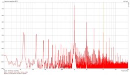
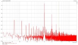
I would like to compare the actual 2nd and 3rd harmonic level to the signal level instead; could someone please share his spectrum measured at 0.1W output so I could see if what I am getting is actually in the ballpark; at the moment my 2nd order is about -40db and 3rd order is about -73db at 0.1W.
I do not know how to run simulation of my exact circuit, but if someone could give it a try it would be interesting to see what sort of THD it would predict at 0.1W?
I used nearly new tubes, so should be no tube related problem.
I did following measurements, all with input signal to get 0.89VRms (0.1W) on the speaker terminal with 8 ohm load:
1) Loop measurement of the soundcard, 0.0025% THD at that level
2) Complete amp with IT, 1.16% THD
3) Complete amp without IT, 1.16% THD (here I adjusted the output of the card to get same voltage on the speaker terminal)
4) Same signal without IT, measured at #26 plate, 0.59% THD
5) Same signal without IT, measured at #45 plate, 1.68% THD
I think the problem I am running into here is that my soundcard input probe with 20db pad has approximately 8K impedance. This means that once I get this probe connected to #26 plate tube sees much less load than normally, so distortion goes up a lot from where it would normally be. This was very clear to see when comparing measurements of #45 plate that, once the probe is connected, works into 3K load (8K//5K) instead of normal 5K transformer load.
This made #45 measure much higher THD on the plate than actual THD on the speaker terminal.
I am wondering if there is something wrong with my measurement setup that would give me high THD number.
I would like to compare the actual 2nd and 3rd harmonic level to the signal level instead; could someone please share his spectrum measured at 0.1W output so I could see if what I am getting is actually in the ballpark; at the moment my 2nd order is about -40db and 3rd order is about -73db at 0.1W.
I do not know how to run simulation of my exact circuit, but if someone could give it a try it would be interesting to see what sort of THD it would predict at 0.1W?
Attachments
45, my 211 amp is all finished and in the chassis, so it would be difficult to "borrow" the first stage; was thinking about the way to do it but it seamed complicated as both stages share same PS...
tcqanh, input transformer I am using is LL7903 wired as 1:4 step-up.
http://www.lundahl.se/wp-content/uploads/2013/05/7903.pdf
http://www.lundahl.se/wp-content/uploads/2013/05/7903.pdf
I tried Loadline simulator that TrippleM suggested (thanks for that link!) and got really interesting result; the predicted THD at my operating point is 0.98%, so really close to 1.16% that I am getting!
So, maybe this is a realistic level to expect if one is using no distortion canceling methods!?
Only thing that I could not quite figure out is why it shows 5K8ohm transformer as 23.1:1 winding; thought it should be 25:1?
Also, per my understanding U-input to 45 grid should be around 8-9V to get 0.1W P-out, even with transformer losses; simulator is calculating 12.67V?
Will get to measure and compare actual voltage.
Attachments
Last edited:
When you calculated the drive voltage did you account for the effect of the reflected load on output stage gain, it's significant.
I'm assuming the output transformer is 5K:8 in which case I also get 25:1 ratio so that is a bit odd.
You need to do something about the 8K input impedance of your measurement set up, it will seriously affect the performance of the driver stage and has a pretty significant effect on the output stage as well. A simple unity gain and 20 dB op-amp stage with a 100K input attenuator would be extremely flexible. I used something similar with +20dB, 0dB, -20dB, and -40dB ranges.
My old 45 amp unfortunately is on long term loan so I cannot measure it, but the distortion at 100mW was 0.4% and predominantly 2nd and 3rd harmonic, not much else. At 1.6W (4K primary) distortion was 4% and again predominantly 2nd and 3rd. The second was dominant in both cases, but 3rd was much higher at full power than at 100mW.. Unfortunately I have nothing more concrete, but my suspicion since the input (not IT!) transformer is exonerated is that the 26 may be having a hard time driving the 45.. More data required. Note that these simple amplifiers do tend to generate significant measurable thd which interestingly enough will not likely be the listening impression you will get in normal use.
Understanding the design limitations/shortfalls is a good thing, whether or not you want to make changes based on those discoveries is another matter. My GM70 design significantly missed the mark in some specification areas, but in all respects meets the auditory criteria to replace the previous amplifier and did. It does outperform the old amp in all areas but missed some performance objectives, including producing rather more distortion than expected, (Sound familiar?) but still less than the amp it replaced.
So I changed my probe to have much larger input impedance, now around 500K.
This made it possible to measure trough the stages much more accurate and it is clear that most distortion is coming from the output stage.
At 0.1W I am getting 1.09%THD at speaker terminal and just 0.043% at #26plate / #45 grid.
At 1W I am getting 3.6%THD at speaker terminal and just 0.11% at #26plate / #45 grid.
I also checked "max power" THD and got 4.77%THD at 1.5W on output?
Now, the question is if I could (and should) modify something in this design to reduce distortion at low power. Obvious choice would be to use 7K or 10K transformer instead of 5K, especially since I am only driving my horns with this amp, so really would never need more then 1W output?
Perhaps a small core, low power transformer with higher primary would help reduce distortion as well as work really well in this "mid and high" frequency range application?
I also measured all signal voltages trough all the stages and all of them look realty good; to have 1W output I measured following Vrms:
0.795V input
3.322V on #26 grid (4.18 amplification on input transformer)
29.17V on #45 grid (8.78 amplification on #26 tube)
78.7V on #45 plate (2.7 amplification on #45)
2.966V on speaker terminal (1/26.5 signal ratio between OT primary/secondary)
Attachments

Also, checked again my signal voltage against the simulator prediction and there is really lots of difference there; to get 1W output with 5K OT into 8ohm I have 29V on #45 grid while simulator calculates 40V; really not sure where this difference comes from; really looks as if there is a mistake in the simulation program?
my amplification on #45 is 2.7; exactly same as predicted by simulation program...
my amplification on #45 is 2.7; exactly same as predicted by simulation program...
Simulations are generally "ball park" so it strikes me that there might be an error in the calculations or in the tube model.
What frequency are these thd measurements performed at? (duh 1kHz lol) The numbers would be expected to be worse at 100Hz than 1kHz for example depending on the transformer.
The distortion performance of the driver is impressively better than I expected.
Potentially the transformer could be contributing to the distortion - any details you can share? It's the last place to look I'd say. You could potentially replace it with a transformer having a somewhat higher primary impedance perhaps even tailored for operation in your target frequency range.
As I indicated at 1.6W I measured 4% thd in my 45 amp long ago so you are in the ball park..
I am a little concerned about the LF spectra and am wondering whether those are artifacts of the measurement set up or actually present in the output of the amplifier at all times. Take a look at magnetic coupling and ripple on the output of the B+ supply. Verify that the raw filament supplies are clean.
Thanks for your comments, I will try to work out the way to use my probes to measure on the primary of the OT/#45 plate; did not have enough attenuation to do that as it would overdrive the soundcard, but with right L-pad should be able to do it.
Will be interesting to see distortion before and after the OT, but I expect that transformer should be pretty good.
It is Tango XE-20S wired as 5K into 8 ohm; here is a link to the datasheet:
http://www.tubebooks.org/file_downloads/tango_tamura/Tango_XE-20S.pdf
Will be interesting to see distortion before and after the OT, but I expect that transformer should be pretty good.
It is Tango XE-20S wired as 5K into 8 ohm; here is a link to the datasheet:
http://www.tubebooks.org/file_downloads/tango_tamura/Tango_XE-20S.pdf
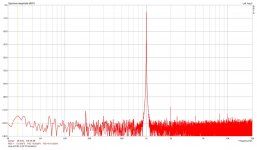
I get this LF spectra when using #26 as my driver; I think it might be because one of the filament transformers "buzzes" a bit which would create some vibration that #26 seem to pick up. When I change driver tube to #10 this LF disappears as it seems #10 is much less sensitive to vibration.
But, even with #26 I can almost not hear it even with my ear next to the horn; they are about 75db down compared to 1W signal.
But, even with #26 I can almost not hear it even with my ear next to the horn; they are about 75db down compared to 1W signal.
Last edited:
Thanks for your comments, I will try to work out the way to use my probes to measure on the primary of the OT/#45 plate; did not have enough attenuation to do that as it would overdrive the soundcard, but with right L-pad should be able to do it.
Will be interesting to see distortion before and after the OT, but I expect that transformer should be pretty good.
It is Tango XE-20S wired as 5K into 8 ohm; here is a link to the datasheet:
http://www.tubebooks.org/file_downloads/tango_tamura/Tango_XE-20S.pdf
The Tango XE-20S has negligible distortion above 100 Hz. This I know for sure. Assuming there is nothing wrong with that DC couple circuit it looks like yours 45's follow average curves (which is what the simulator uses) which isn't great as individual tubes can be quite better. All 45's I have are very linear for small output swing even for low load impedance. The only generate 2nd harmonic and a barely measurable 3rd. If this is the case I think you might improve a bit going for 7-10K (which you can try just loading the 8R tap with 11-16R, this will not make a big difference @ 1KHz) but not so much if the linearity is an issue and Pout will be quite less.
- Status
- Not open for further replies.
- Home
- Amplifiers
- Tubes / Valves
- Distortion expected in SE DC coupled 26/45 amp