At this point, honestly, I've no idea how or why carrier based/non carrier based feedback topologies should differ, an area of much confusion and very little information, Sir, you serve this forum well. Take your time with it, we can wait for the good stuff.
The main difference is that you have to struggle for not getting into unwanted self-oscillation with carrier based topologies, specially when feedback is taken after the main output filter. With a self oscillating toplology any phase shift (including the output filter's) can be used intentionally to achieve the desired oscillation.
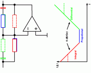
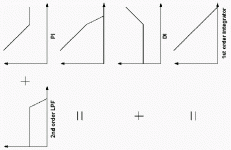
your plots (noiseshaper like) show gave reason to suspect that your amp have second feedback loop above modulator?
The order of the noise shaper is even higher than 2nd order. But you recognised correctly that it IS a noise shaping topology ! 😎
I suspect that a deltasigma amp can sound OK but you really need to go to 5th order or so.
The one that I heard in action so far did even have a 7th order loop (sharp SM-SX100). Measurements however are not as good as this loop order, at the given sampling rate, would (theoretically) promise.
Sound-wise I must say that it isn't bad at all. But for the given price and technical effort it is easily outperformed by conventional amps. I was expecting the sound to become worse at low listening levels (what it actually definitely must, it's just a matter of how we perceive it) and therefore asked the salesman to turn down the volume significantely. I went up to the speakers and listened from close proximity and I must admit that the developers did a good job: No hiss, no roughness. I think the scanting salesman is still wondering why I did that (while his lying in his bed awake), although this is about four years back already !😀
Regards
Charles
Hi Charles,
The sharp amp was an EMI inferno, the output filter used highly nonlinear toroids, the noise shaper was switched cap which aliased HF components back into the audio (as noise and tones) and the layout was something even a freshman should be ashamed of.
I'm sorry to report that such lack of understanding and craftsmanship is typical of Far-East (including Japan) electronics. They are absolute geniuses at tweaking variables on a set system (e.g. process parameters in materials processing), but system-level thinking is something which the West does better. I read somewhere "let them make a transistor and it's wonderful but do not entrust them with the design of a spaceship". Too true. Have a look at the state of the hardware they've placed into orbit and sent to Mars the last few years.
I presume you are more knowledgeable in class D than sharp and hence will use:
*A continuous-time loop
*Differential processing
*Gapped ferrite cores
*Preferably feedback after the filter (you know where the poles are. Now go and look where to put the zeros).
Cheers,
Bruno
Hi Bruno
The most interesting thing is that it took them eight years to develop it. They also have tons of patents on details I wouldn't bother to apply for one.
It is also interesting that one doesn't hear much about their class-d implementation anymore though they once mentioned that they wouldn't use any conventional amp in the near future anymore.
Refering to your other statements:
Definitely, specially when you go for discrete ! Why make something more complicated and technically inferior at the same time ?
Probably
Wouldn't dare to use anything else for any type of switching amp !
Definitely for an amp that is used by me and where I know what is connected to it in advance.
Regards
Charles
The most interesting thing is that it took them eight years to develop it. They also have tons of patents on details I wouldn't bother to apply for one.
It is also interesting that one doesn't hear much about their class-d implementation anymore though they once mentioned that they wouldn't use any conventional amp in the near future anymore.
Refering to your other statements:
*A continuous-time loop
Definitely, specially when you go for discrete ! Why make something more complicated and technically inferior at the same time ?
*Differential processing
Probably
*Gapped ferrite cores
Wouldn't dare to use anything else for any type of switching amp !
*Preferably feedback after the filter
Definitely for an amp that is used by me and where I know what is connected to it in advance.
Regards
Charles
Hi Again!
.... OK, my current thoughts for my amp are now:
- still full bridge, because of power supply rejection
- still PWM Controller UC 3823 A, but increased
switching frequency around 150kHz.
- lowered rail voltage around 90V.
- MosFets: IRFB52N15D
- Halfbridge driver: still looking, but this one seems interesting:
http://www.national.com/ds/LM/LM5104.pdf
Which half bridge drivers do you use?
Also glad to see that you propose:
-continuous time loop
-gapped ferrite cores
But until I read your posts, I would have not dared to pick the feedback from behind the output filter. I would have been afraid
of the heavy phase jump of that LC filter and would have tried a feedback with a simple RC filter.
Hm...., yes I know the poles.... and I fear them!
On the other hand: As I only need that amp for low frequencies, I could easily decrease forward gain early.... hm...
Cheers
Markus
Hi,
Keep in mind they are talking about phase shift pwm which makes taking the feedback after the filter easy!
The HIP2101 half bridge driver seems ideal. It's specs are much improved over the similar IR2101. Glad to see you're back at it.
Keep in mind they are talking about phase shift pwm which makes taking the feedback after the filter easy!
The HIP2101 half bridge driver seems ideal. It's specs are much improved over the similar IR2101. Glad to see you're back at it.
Hi Markus
Do you know what a PID controller is ?
If you post your schematic i'll try to help with component dimensioning.
Regards
Charles
Do you know what a PID controller is ?
If you post your schematic i'll try to help with component dimensioning.
Regards
Charles
Hi,
I know what it is.....hahaha.......try to implement/design one.........ffffffforrrrrrrrrrget it!!!.....thats' why I gave up my mueta clone..... well beyond me.
I know what it is.....hahaha.......try to implement/design one.........ffffffforrrrrrrrrrget it!!!.....thats' why I gave up my mueta clone..... well beyond me.
Hi!
thanks for the hint with the phase shift PWM...
... did not notice that before!!
...will also have a look to the HIP2101.
PID ??
Ähem, if I hear PID, my brain always links to complicated math models of the cybernetic control engineering.
P: proportional
I: integral
D: time differential...
...and tons of Laplace transformation...
To be honest: I prefer to solve my regulation circuits with
the bode diagram as my brain can handle this much easier
and faster. If I put a PID regulator to the bode diagram, then this visualisation normally helps me much more than the Laplace transformation.
In Laplace transformation I can only follow strict math rules, but my brain never developed a proper feeling if the calculation is going to the right direction or not...
🙄
But I assume that is not your point, when you say PID controller.
I did not draw the schematic. But it might be the right time to transfer the schematic from brain to paper. I will post it within the next days.
My plan for practice was to start with the PWM first, get it running to drive a headphone (with small filter), without the MosFet bridge... and then in next step I would add the powerful stuff....
Great that you offer your direct support!!!
Bye
Markus
... your PID is exactly my PID....
Glad to see, that you also seem to be a friend of 'Bode' !
...sorry, must leave now--- some friends are already waiting...
Bye
Markus
Glad to see, that you also seem to be a friend of 'Bode' !
...sorry, must leave now--- some friends are already waiting...
Bye
Markus
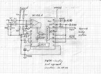
PWM schematic
Hi Guys!
This night is the perfect night to put the
schematics of my first theoretical approach to
this forum.
I will start with the PWM section.
(The BRIDGE section will follow in the next posting)
I have some enhanced version of the standard PWM control
"xxx3825" with me. The UC 3825A. I will run it voltage mode.
RT (15k) and CT (1n) are setting the PWM frequency to 150kHz.
Nice point of the UC 3825 it also delivers the inverted PWM
signal. Great, this helps me to drive a full bridge by two
simple half bridge drivers...
Gain & frequency compensation:
The sawtooth of the UC3825 ramps between 1V and 2.8V.
This difference will correspond to -90V .... +90V at the output.
So the gain behind the OP amp is 100 (40db).
For my first approach I would try to drop the overall
forward gain to 0db at 31kHz by simple integration,
as at 31kHz we will have the heavy phase jump of the output filter.
For lower frequencies the phase shift will be dominated by the
90° of the integrator (...neglecting some nanoseconds delay of the
UC3823 and power bridge).
My closed loop is designed for 20db gain. So feedback will drop
to 0db at 3.1kHz. Quite restrictive, I think....
But at the relevant signal frequencies below 45Hz, this will still
give reasonable 37db feedback.
For this the OP amp circuit (without feedback from speakers) must be
down at -40db at 31kHz, which is ensured by the integration cap
of 270nF. Probably I can try higher feedback, later in the real
circuit.
Please find attached the schematic of the PWM section.
Looking forward to your comments
Markus
Attachments
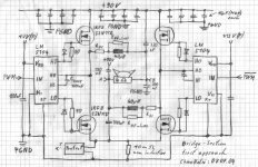
BRIDGE schematic
BRIDGE section:
The IRFB52N15D offer 150V / 32mOhms / 60A and a low gate charge around 60nC...70nC. I hope that I do not need external freewheeling diodes.
Which experiences did you make with the integrated body diodes of MosFets?
If you are using external diodes: Which types showed good results?
I still think that the LM5104 are nice half bridge drivers, especially their adaptive dead time seems to be exactly what I need. The Chip detects the gate-source voltage of the MosFet which is beeing turned off. It does not turn on the other MosFet before the first MosFet is really showing a low gate source voltage.
Sounds nice and promising.
But in fact the real thing might still need some correction....
Also it is fine for me that the LM5104 uses a single PWM input and
generates both gate signals from this, which is matching nice to my
plans in the PWM section. Also the LM5104 has an integrated boost diode for the supply of the high side driver....
http://www.national.com/ds/LM/LM5104.pdf
Filter:
Rdc is simply the copper resistance of the wire.
RHF_Loss reflects the losses in the core and the high frequency losses in the winding. 40uH for 30Amps will be fun to design (love that stuff) ...
I decided to use symmetrical split filter caps. For HF the 330nF to ground and the 330nF towards 90V are in parallel. They will have to carry a lot of HF current, so I would probably have to parallel some high rated types anyway....
HF-blocking of the 90V rails.
I think I will need a battery of large MKP caps for the 90V rail as close as possible to
the MosFets....just a guess... Any experiences available?
Here is the schematic of the BRIDGE section.
Bye
Markus
Attachments
Hi Markus,
I used irfb52n15d in sub amp +/-50v to 2ohm load, 5 day ago, and find they pretty easy to open/close, like irf540n or so. I'll try forget irf3415 -nightmare, very heavy fet, but irfb53n15d($2) 1.5 times more expensive. Fairchild's fets, which our pro guys loves, unfortunately isn't found in accessible price list.
I used irfb52n15d in sub amp +/-50v to 2ohm load, 5 day ago, and find they pretty easy to open/close, like irf540n or so. I'll try forget irf3415 -nightmare, very heavy fet, but irfb53n15d($2) 1.5 times more expensive. Fairchild's fets, which our pro guys loves, unfortunately isn't found in accessible price list.
Hi Markus.
You cannot use this PWM IC in this fashion. The driver outputs are toggled in order to control a push-pull SMPS topology. If you want to use this IC you will have to OR the outputs and do the inversion of the control signal for the second half of the bridge by yourself.
There seems to be an UC3823 variant without the toggle function (the version without suffix A).
RE feedback: Your loop gain is O.K. for playing around first, but I assume you will soon want to increase the unity-gain point up to 70 kHz approx. 😉
Regards
Charles
Hi Ivan!
...yes price is not very convenient, especially I am still looking for
a distributor in Germany who offers them without horrible shiping costs.
On the other hand.. it's a DIY project, not a cost optimized design
for professional mass production... So I tend to pay more in order to get high performance. And your positive experience with the technical performance of the IRFB52N15D also pushes me to try them.
So your are also using them without external diodes, right?
Hi Charles!
Uhps, seems like I did not read the data sheet of the
UC3823A careful enough. Thanks, for the hint. I will rework this topic.
...glad to see that your opinion on my feedback is perfectly matching
my thoughts.
Bye
Markus
...PWM controllers...
...hm, yes... definitely the UC 3823A is not what I need....
Thanks again Charles, your comment saved me at least one
day!
I must admit: Who can read- takes advantage! ..should really read data sheets more careful in future.. 🙄
🙄
...well, I started to look around for suitable PWM controllers, but it seems that most of them have already integrated the toggling flip flop for push pull applications...
UC3823 (without A) as proposed by Charles seems to be closer to what I need , but not offering inverted output, ...will check suitability in detail...
Bye
Markus
...hm, yes... definitely the UC 3823A is not what I need....
Thanks again Charles, your comment saved me at least one
day!
I must admit: Who can read- takes advantage! ..should really read data sheets more careful in future..
🙄 ...well, I started to look around for suitable PWM controllers, but it seems that most of them have already integrated the toggling flip flop for push pull applications...
UC3823 (without A) as proposed by Charles seems to be closer to what I need , but not offering inverted output, ...will check suitability in detail...
Bye
Markus
ChocoHolic said:Hi Ivan!
...yes price is not very convenient, especially I am still looking for
a distributor in Germany who offers them without horrible shiping costs.
On the other hand.. it's a DIY project, not a cost optimized design
for professional mass production... So I tend to pay more in order to get high performance. And your positive experience with the technical performance of the IRFB52N15D also pushes me to try them.
So your are also using them without external diodes, right?
Hi Charles!
Uhps, seems like I did not read the data sheet of the
UC3823A careful enough. Thanks, for the hint. I will rework this topic.
...glad to see that your opinion on my feedback is perfectly matching
my thoughts.
Bye
Markus
Two sugestions,
1. Make good use of fairchild's free samples
2. Why not check out our reference design thread
- Status
- Not open for further replies.
- Home
- Amplifiers
- Class D
- Distorsions in class D