Jjazz,No, you could use that supply, just make sure the GND output is isolated - floating.
No, aim between 26V and 27V.
I wouldn't use a dual supply because the GNDs may be connected meaning you couldn't use it for both the 8V and 26V supplies.
Sounds expensive and overkill.
Why not just get some verro board, diodes, resistors, and caps and have a go at building your own?
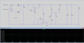
I've attached a sim of a circuit that is easy to build yourself on vero board. It sims at under 200uV ripple.
Ryan
You may want to use a 25V + 25V transformer instead to give the LM317 a bit more headroom and increase the values of C3 C4 R4 R5 to provide better filtering. eg: 1000uF / 7R.
Cheers
Hi Ryan!
You're right Ryan, it's very expensive, and I'm still not sure if the end result of the dac is good for me and spending less money is a good idea.
I will use the standard power supplies that I have and I will try to make this power supply. I have no knowledge of electronics, I am a component assembler, but I think that diagram is easy to understand and do with the help of a friend with that knowledge.
Thank you very much for your help, I am very grateful.
Update
Hi Guys,
Fabrication for all orders is almost complete.
Thanks very much for giving me the opportunity to provide this service to you.
I will start accepting new orders as of now.
Ryan
Hi Guys,
Fabrication for all orders is almost complete.
Thanks very much for giving me the opportunity to provide this service to you.
I will start accepting new orders as of now.
Ryan
Jjazz,
You may want to use a 25V + 25V transformer instead to give the LM317 a bit more headroom and increase the values of C3 C4 R4 R5 to provide better filtering. eg: 1000uF / 7R.
Cheers
Hi Ryan!
I retake the project in its final phase (many pieces and lots of money). I'm going to order the pieces and I have two doubts.
The first if the secondary transformer for this scheme should be + 25.0.-25?
And the other is if the resistance of 7ohm can be 2w instead of 1w and tolerance of 5%. This is ok?
Best regards
Hi Jjazz,
Yes you could use 2W at 5%, no problem.
For the transformer, yes you could use a 50V CT (25-0-25), or you could use one with two separate 25V windings.
Ryan
PSU
Hi guys,
I might give this set up a go. Ill try it without the zener reg also.
The darlingtons could be BD679 and BD680. The npn bjt could be MJE243G.
I've not tried this so just remember that if you build this.
The output has 1uV per division. The ripple before the cap multi is about 560mV peak to peak.
The transformer I modeled was a 24V+24V.
If I try this and it works well I might make a PCB.
Attachments
Hi!
I'm sure he's put somewhere, but I can't find him.
Which is the consumption of the 8 volt connection. I need it to order the transformer. What values would be appropriate.
Thanks
I'm sure he's put somewhere, but I can't find him.
Which is the consumption of the 8 volt connection. I need it to order the transformer. What values would be appropriate.
Thanks
Hi!
I'm sure he's put somewhere, but I can't find him.
Which is the consumption of the 8 volt connection. I need it to order the transformer. What values would be appropriate.
Thanks
Current draw is about 45mA for the 8V supply.
I received by board, really impressive in all aspects, Thanks Ryan.
Really glad you like it!
I wish you all the best with your project.
Cheers.
8V and 26V PSU
If I just use LM317 based PSU; shouldn't it be fine for 8V and 26V? The board already has upstream local regulators to supply +-5V and -15V. LM317 is old and has just average performance. Or should we use state of the art super regulator PSU?
I am trying to get a sense of importance of 8V and 26V for this board.
Using a 317 may be a good starting point, but i would suggest to have a play around with different circuits using different filtering techniques and have a listen to see if you like the sound or not. Having a regulator before the onboard regulator is not necessary, you could just use a basic rectifier with CRC/CLC or whatever tickles your fancy.
No, you could use that supply, just make sure the GND output is isolated - floating.
No, aim between 26V and 27V.
I wouldn't use a dual supply because the GNDs may be connected meaning you couldn't use it for both the 8V and 26V supplies.
Sounds expensive and overkill.
Why not just get some verro board, diodes, resistors, and caps and have a go at building your own?
I've attached a sim of a circuit that is easy to build yourself on vero board. It sims at under 200uV ripple.
Ryan
Hi Ryan!
I hope the holidays are going well.
I'm taking advantage of the holiday to mount the DAC.
I have a problem with the 26v power supply. I followed your design and the output voltage is DC 25.2 V , not the expected 26v. The input AC voltage oscillates between 25.2 and 25.5 V (I don't have good electrical power at home).
There is something I can do to get the 26v, maybe some check to see that everything is fine (I think it is or would not give those 25.2v)
Thank You very munch.
Best regards
Hi Jjazz,
Check the voltage going into the LM317, it needs at least 2V across it. If that is the case then use lower value resistors in the CRC. You may be getting lower voltage due to a low mains voltage.
Correction
*ref LM317 datasheet (Input-to-output differential voltage)
Hi Jjazz,
Check the voltage going into the LM317, it needs at least 3V*across it. If that is the case then use lower value resistors in the CRC. You may be getting lower voltage due to a low mains voltage.
*ref LM317 datasheet (Input-to-output differential voltage)
Hi, Happy New Year!!
I have a problem, the output of -5v of PCB 1541, measures 5v (positive). It is other measuring points of the PCB measure correctly. Does anyone know what might be wrong? (I have correctly measured hahaha).
Thanks
I have a problem, the output of -5v of PCB 1541, measures 5v (positive). It is other measuring points of the PCB measure correctly. Does anyone know what might be wrong? (I have correctly measured hahaha).
Thanks
hello i received my board...
do i need the 8v and 26v powersupply or only the 26v???
does anyone know if the salas SSLV1.1 BiB is a floating ps???
could i use it?
do i need the 8v and 26v powersupply or only the 26v???
does anyone know if the salas SSLV1.1 BiB is a floating ps???
could i use it?
Hi, Happy New Year!!
I have a problem, the output of -5v of PCB 1541, measures 5v (positive). It is other measuring points of the PCB measure correctly. Does anyone know what might be wrong? (I have correctly measured hahaha).
Thanks
The labels on the -5V are the wrong way around. So your measured voltage is correct. I hope you have dummy loads or a chip in the slot while measuring the voltage, otherwise the pass PNPs will get HOT. 😱🙂
hello i received my board...
do i need the 8v and 26v powersupply or only the 26v???
does anyone know if the salas SSLV1.1 BiB is a floating ps???
could i use it?
Yes you need the 8V supply, this is for the attenuators. Using the SSLV1.1 BiB may be ok as long as the outputs are kept floating, but using a shunt reg to feed another shunt reg is not necessary.
My plan for my 26V supply:
Rectifier->2200uF cap -> capacitance multiplier in positive and negative line -> common mode choke -> 1000uF and 1uF-> 26V input.
- Status
- Not open for further replies.
- Home
- Group Buys
- Distinction-1541 v2 complete PCB interest list