I posted some statistics a while back in this thread, with the mean and standard deviation of Idss and Vgs for 100uA Id for a batch of BF862 from the same date code. They are fairly wide-distribution, compared to reports I've gotten privately for the Toshiba 2SK117. Note as well that NXP does not offer an Idss sort. None that I tested were out of spec, but one came close on the low end for Idss.Been there! Done that! I'm interested in people who have DONE IT and interested in avoiding the pittfalls and interested in the circuit parameters of the SWOPA that I should be looking for; what optimum voltage, what optimum Idss of the BF862. They are probably all over the map out of a sample of 100. Thanks, Ray
Thanks! Very helpful. Yes, I noted that. Some matching circuits I see on the web are all over the place complexity wise.
Digital JFET Test Rig
Digital JFET Test Rig
Curve looks pretty smooth to me, here's a zoom in of that area:This is looking better, but there also still seems to be a kink at the transition. The problem for me was simulating the null of seconds for a simple phase splitter. It always walks down to the kink, where a real device has a sweet spot with a very deep null.
The level 3 model has an ALPHASP parameter that fits the entire curve smoothly with a tanh function which has a continuous derivative.
What did you end up using for lambda and B, and did B start doing something?
You might ask why something as fundamental as lambda is so far off in the extracted model.

Currently I'm using a Lambda=6, B=0.37. B has always done something, but depending upon the other parameters it can be very subtle. These are easily massaged in various directions without major hiccups, alter the curvature in the transition area.
Biggest problem is that Ids vs. Vgs curve is now almost linear, which is probably the reason for the published model being such. As mentioned before, you can get around this by adding a Vgs dependent voltage source at the gate; may not be correct procedure, but if the model flies ...
Frank
Exactly. Still need to add a voltage source at the gate, and to try some more tests; if anyone has other test rigs for JFETs it could be very handy ...IMO curve fitting as used here is often a sub for an incomplete model. but often necessary and useful.
what model is being used and is it complete?
Frank
If one needs to know what the transistor characteristics "really" are for the part you will be using in a circuit.... get a characteristic curve tracer.... used TEK (576). Or, you can get a new one from Chinese company which will display two devices at the same time on the crt screen (yes, crt). Good for matching. Cost new including shipping is $800. Or play with a couple PC based curve tracers developed by Elecktor or other here in a forum. measure the transistor and put all the values you measure plus some from data sheet, perhaps, into sim or just build with them from your measured information. -Thx RNM
Last edited:
RB & rbb'
I'm looking at Noise performance for this & other circuits.
For good LN transistors, noise can be modelled simply with rbb'
From what I can see, RB = rbb' in SPICE
I can get a good estimate of rbb' from noise contours to replace the default RB = 10R which is far too optimistic for audio noise.
What are the other implications and are they small, eg VHF & UHF response, if I just change RB?
I note the default LTspice BC547s have superb RB=1R 🙂. Wish I knew where they bought their stuff. 😀
But even Cordell's stuff is suspect. His npn 2n4401C has RB=13 while the pnp 2n4403C has RB=38 which is more believable and closer to Bcarso and my own Jurassic measurements. I've always found npn to have higher rbb'
I get rbb' from the high current 1kHz noise contours and that's been pretty good for me.
I know rbb' at 100MHz may be different but if I just change RB, to get closer to real life audio noise, will I be mucking up my ability to see 100MHz oscillation? 😕
CMR ?
What is the CMR of the SW-OPA? If -100DB for thd is a good number to shoot for, I think same (-100) would be good for CMR.
What is the CMR of the SW-OPA? If -100DB for thd is a good number to shoot for, I think same (-100) would be good for CMR.
Sim'ers --- use worse case conditions: Input source Z of 1K-10K and C/L gain as low as is stable design (X2-3?).What is the CMR of the SW-OPA? If -100DB for thd is a good number to shoot for, I think same (-100) would be good for CMR.
Some generalities about CMR that I am focusing in upon - THD is proportional to CM voltage squared for voltage changes --- at low C/L gains; and maybe this relates to PIM??? --> Phase Modulation from b-c or g-d capacitance being changed by CM signal. When and which topologies are affected most and how much. How much can PM be reduced by cascoding? References? Thx - RNM
Last edited:
CM induced thd. Asym waveforms have a CM component. Need to have best CM performance for music appls. Thx-RNM
Any pcb made yet?
I have some unexpected extra time to work on my prototype, "real" breadboard first for me. This is taking the idea of a rainy day project to extremes.
I have started a breadboard but it's to92 transistors that I had already matched and RN60D resistors. In the JE990 by Jensen/Harris, I talked with them back when and they preferred a pn2484 out of all transistors for the current mirrors. This is avaliable in SMT as mmbt2484. Why did they choose that transistor? Thanks, Ray
I gather you are in the eastern part of the country. My condolences. A friend has business there and was planning on leaving for NYC on early Friday morning. I wonder if things will even have stabilized by then? Had it not been for the biz she'd be joining me at a club to hear her stepfather Bill Holman's big band 🙁I have some unexpected extra time to work on my prototype, "real" breadboard first for me. This is taking the idea of a rainy day project to extremes.
I gather you are in the eastern part of the country. My condolences. A friend has business there and was planning on leaving for NYC on early Friday morning. I wonder if things will even have stabilized by then? Had it not been for the biz she'd be joining me at a club to hear her stepfather Bill Holman's big band 🙁
As these things go he will have no problem. Our story is even stranger, we were at a wedding in Chicago Sunday and when we saw all flights were cancelled till Wed we did a one way car rental and left right from the reception. Back in Boston 16Hr. later and literally 30min. before the SHTF.
Any pcb made yet?
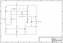
Nope, not yet. However, I'm doing a cut-down, 8-BJT single-ended version of SWOPA, for which I've completed the Eagle schematic as well as preliminary placement. I'm also planning an SMD version with 4x SOT363 duals later.
Attachments
Last edited:
Still need someone to do pcb for SW-OPA
🙁🙁 So, we have no one making a SW-OPA pcb right now. rats !
🙁🙁 So, we have no one making a SW-OPA pcb right now. rats !
Everyone is waiting for someone to breadboard Scott's OPA and making the REAL world parts substitutions and corrections and that person should be Scott. I matched several hundred 2n4403 and 2n4401,(to92) and do not want to go through that pain again, I'm waiting before I buy more parts. 2SK170 can be bought already matched. There is a guy in Israel matching them to high tolerance. Ray
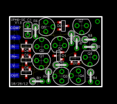
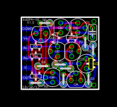
Here's the PCB layout of the 8-BJT single-ended SWOPA-SE, about 0.75"x0.85". It will use the same base PCB as my existing LF03 discrete opamp.
Edit: The BJTs can be any TO92 BCE-leadout pair like the 2sa1015/2sc1815 or similar. The dual diodes can be BAV99 or similar. Resistors are sane values, exact values TBD after prototyping in 4-8 weeks.
Edit: The BJTs can be any TO92 BCE-leadout pair like the 2sa1015/2sc1815 or similar. The dual diodes can be BAV99 or similar. Resistors are sane values, exact values TBD after prototyping in 4-8 weeks.
Attachments
Last edited:
Everyone is waiting for someone to breadboard Scott's OPA and making the REAL world parts substitutions and corrections and that person should be Scott. I matched several hundred 2n4403 and 2n4401,(to92) and do not want to go through that pain again, I'm waiting before I buy more parts. 2SK170 can be bought already matched. There is a guy in Israel matching them to high tolerance. Ray
Right now that's what I have on hand 4401/4403's and will use that for a proof of concept i.e. the performance improvements of other devices is either higher-voltage related or some very subtle performance issues. If the pinouts are the same (or rotationally the same) there would be no problem proceeding. Matching also is not a work/not-work issue.
FYI, Diodes Inc. offers 4401/4403 in a SOT 363 dual configuration (NPN+NPN, PNP+PNP and NPN+PNP), the prefix for duals is MMDT and the complementary version is 4413. The same chip is also available in single SOT23 and, of course, TO92. All those parts seems to be globally available through standard channels.
- Home
- Source & Line
- Analog Line Level
- Discrete Opamp Open Design