For people's information, I just tried the model of the BF862 that's being used in LTspice, and it does add a gentle curve, slope decreasing towards zero gate voltage, to the transconductance characteristic; a simple, minimal spec'd set of parameters for a JFET just traces a straight line, otherwise.
Frank
Maybe a picture would help. I suggest gate shorted to source and sweep the drain voltage plotting Id, I don't see the B parameter doing anything and the curves are still fit as before.
jfets as cascode devices has an impedance advantage over bipolars... so while capacitance is lower with bipolar the impedance is also lower, so the current swing over rail resistors add more distortion due to waring drive current. each type has their over benefits in cascoding
IMO -- unless you are going for the record in low thd, the distortion reduction due to cascoding will be minimal with high gnfb design. Better to spend time on PSR and CMR. Which cascode in a diff amp input will do better for those parameters? Thx-RNM
The "Rush cascode" series differential used in the second stage can help with power supply immunity, and is itself improved with conventional cascoding:

Thanks,
Chris
Thanks,
Chris
Nicely called, Scott, no cigar ...Maybe a picture would help. I suggest gate shorted to source and sweep the drain voltage plotting Id, I don't see the B parameter doing anything and the curves are still fit as before.
Original results:


Altered test rig as suggested, and got:

From the LTspice help:
The JFET model is derived from the FET model of Shichman and Hodges extended to include Gate junction recombination current and impact
ionization. The DC characteristics are defined by the parameters
VTO and BETA, which determine the variation of drain current with
gate voltage; LAMBDA, which determines the output conductance; and
Is, the saturation current of the two gate junctions. Two ohmic
resistances, Rd and Rs, are included. Charge storage is modeled by
nonlinear depletion layer capacitances for both gate junctions;
which vary as the 1/2 power of junction voltage and are defined by
the parameters Cgs, Cgd, and PB. A fitting parameter B has been
added. See A. E. Parker and D. J. Skellern, An Improved FET Model
for Computer Simulators, IEEE Trans CAD, vol. 9, no. 5, pp. 551
553, May 1990
Frank
Nicely called, Scott, no cigar ...
Original results:
View attachment 308141
View attachment 308142
Altered test rig as suggested, and got:
View attachment 308143
From the LTspice help:
Frank
The second graph is not realistic. The sub-saturation curvature transitions abruptly to a linear function. Despite the promising description in Help, it doesn't seem to realize correct behavior.
So it goes.
Exactly ... so, at the moment, "no cigar", not good enough ... 🙁The second graph is not realistic. The sub-saturation curvature transitions abruptly to a linear function. Despite the promising description in Help, it doesn't seem to realize correct behavior.
So it goes.
I'll have a bit of a look around, and a play, see what might be possible ...
Frank
what are the actual formulas used in the sim code? whats does the sim software do with the data? If a math major did the code, it might be a lot different than if a device physics major did it. Is curve fitting used?
We may have some good news, people ... the Lambda parameter - channel length modulation - is crucial, and may have been set completely wrong in the published model. Playing with figures pulled out of the air I now get curves that look exactly like they're supposed to for the Ids vs Vds plot, but in the wrong place. So I'll start fiddling with other parameters, and see if I can get it to fully behave ...
Frank
Frank
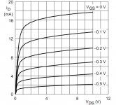
Just to show how close one can go to matching the JFET curves, below is a grab from the BF862 datasheet, and LTspice's version thereof with modified parameters. There is still a problem unresolved, because the constant Vgs curves shown have been fudged, LTspice keeps insisting on equal spacing of curves between equal stepped values -- those shown represent other than Vgs of -0.1 through to -0.5. Which means that the curve of drain current as a function of gate source voltage doesn't match the datasheet.
This can be circumvented by adding a behavioural voltage at the gate, but maybe there's some fine tuning elsewhere that can be done ...
Frank
This can be circumvented by adding a behavioural voltage at the gate, but maybe there's some fine tuning elsewhere that can be done ...
Frank
Attachments

This is looking better, but there also still seems to be a kink at the transition. The problem for me was simulating the null of seconds for a simple phase splitter. It always walks down to the kink, where a real device has a sweet spot with a very deep null.
The level 3 model has an ALPHASP parameter that fits the entire curve smoothly with a tanh function which has a continuous derivative.
What did you end up using for lambda and B, and did B start doing something?
You might ask why something as fundamental as lambda is so far off in the extracted model.
Last edited:
IMO curve fitting as used here is often a sub for an incomplete model. but often necessary and useful.
what model is being used and is it complete?
what model is being used and is it complete?
Last edited:
I would like to see the schematic of a simple circuit to match jfets BF862 at the voltage they are gona work most linearly in the circuit. I have one for BJTs. Thanks, Ray
But obviously if I'm gona built a circuit to match jfets then it would be nice to match p channel as well. All I'll probably have to do is reverse voltage polarity??? Thanks, Ray
It would be nice to measure pinch off voltage on a p channel jfet. I've just never done it. Thanks, Ray
Been there! Done that! I'm interested in people who have DONE IT and interested in avoiding the pittfalls and interested in the circuit parameters of the SWOPA that I should be looking for; what optimum voltage, what optimum Idss of the BF862. They are probably all over the map out of a sample of 100. Thanks, Ray
- Home
- Source & Line
- Analog Line Level
- Discrete Opamp Open Design