The PWM 1-bit output is not the same beast as 1-bit DSM. It is closer to multi-bit one with variable phase shift and bandwidth. It is not perfect of course, just another trade off better fitting analog output.

The advantage of building a discrete DAC with an FPGA is easily incorporating crossovers. Compared to analog crossovers, digital ones are vastly superior. Reverting to analog in commercial products can compromise both price and performance, making it less than ideal.Hope to see a multichannel one and we can do digital crossover on it.
Yeah I'm doing DSP XO now but my source only have 4 channels so I have to use hybrid DSP/passive XO for 3 way system...
Hi, do you know and could share with us what are the differences between ess9039pro and ess9038pro? Only the newer version of hyperstream modulator?Take ES9039Pro, shift input 32bit data right twice, reducing SNR by 12dB and probably all of the harmonics will be swamped in the noise floor.
0dbFS signals don't make any sense if you have 32bit input and SNR ~140dB, just keep input a bit lower.
There are very few comparisons between these two.Then there was ES9038PRO from ESS that many folks thought must sound perfect because it measures so well. Then ES9039PRO came along and finally it sounds better. Why? Is whatever it was that they fixed something that showed up as a substantial improvement in SNR?
I might be wrong but ess9039pro looks like "easier to work with version" of ess9038pro, master clock frequency is lower etc.
For some reasons the newest Weiss uses ess9038pro not the ess9039pro:
https://www.stereophile.com/content/weiss-engineering-helios-da-processor-measurements
I have seen very good THD measurements of 9039 presented by IVX.
As usual, well designed SDM have significant THD only at signal level close to 0dBFS.
At -10dBFS distortions can be made unmeasurable. So, if SDM has enough SNR, it makes sense to drop a bit of it for the sake of almost zero THD. I actually don’t care what ESS is doing.
As usual, well designed SDM have significant THD only at signal level close to 0dBFS.
At -10dBFS distortions can be made unmeasurable. So, if SDM has enough SNR, it makes sense to drop a bit of it for the sake of almost zero THD. I actually don’t care what ESS is doing.
Last edited:
Couple of weeks ago I found a few hours for experimenting with the DAC.
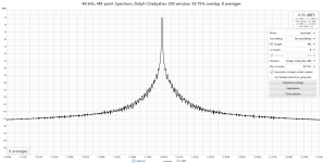
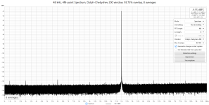
1. Just tuned values of passive components of reconstruction filter to improve SNR.
Now unweighted SNR is close to 112dB @ 48KSPS. That gives about 18+ ENOB.
2. Added couple of J-tests, narrow 12k+-10Hz and wide - 1 to 20k range.
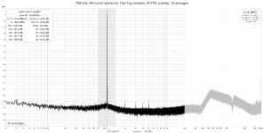
The legend of the images is: J-narrow, J-wide, Typical THD, measured at 768SMPS (noisier than at 48KSPS).
Estimated phase noise at 10Hz offset from 12KHz approximately = -((152-10)-db(10/(48e3/2^22))) = -83.17dBC/Hz
Note: input from optical TOSLINK interface.
1. Just tuned values of passive components of reconstruction filter to improve SNR.
Now unweighted SNR is close to 112dB @ 48KSPS. That gives about 18+ ENOB.
2. Added couple of J-tests, narrow 12k+-10Hz and wide - 1 to 20k range.
The legend of the images is: J-narrow, J-wide, Typical THD, measured at 768SMPS (noisier than at 48KSPS).
Estimated phase noise at 10Hz offset from 12KHz approximately = -((152-10)-db(10/(48e3/2^22))) = -83.17dBC/Hz
Note: input from optical TOSLINK interface.
Attachments
Last edited:
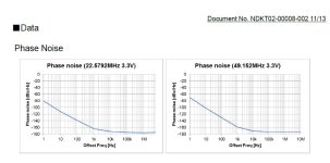
It is interesting that my estimate of the phase noise of the DAC exactly matches the datasheet of Crystek CVHD-957.
So, if you see some measurement looking much better than in the post above be a bit suspicious.
This is an image from CVHD datasheet, it has the same -80dBC/Hz at 10Hz.

So, if you see some measurement looking much better than in the post above be a bit suspicious.
This is an image from CVHD datasheet, it has the same -80dBC/Hz at 10Hz.
Noise skirts around the fundamental contain both AM noise and PM noise. AM noise comes mainly from Vref (DAC & ADC). So getting same noise level at 10Hz between noise skirts and clock datasheet phase noise plot is quite likely incidental.It is interesting that my estimate of the phase noise of the DAC exactly matches the datasheet of Crystek CVHD-957.
So, if you see some measurement looking much better than in the post above be a bit suspicious.
This is an image from CVHD datasheet, it has the same -80dBC/Hz at 10Hz.
There are clocks with lower phase noise than CVHD-957. E.g. NZ2520SDA which I mostly use has about 20-30dB lower phase noise at 10Hz according to datasheet. So measurements looking much better may just be using better clock (and Vref).
Attachments
Understood, looks like the skirts on FFT are not relevant to the clock jitter at all.
To measure oscillator jitter/p-noise correctly,
you need to transfer the clock frequency to DC using the same oscillator as reference for RF mixer.
Today I measured -130dBc/Hz at 12k+10Hz with a little improved setup🙂.
To measure oscillator jitter/p-noise correctly,
you need to transfer the clock frequency to DC using the same oscillator as reference for RF mixer.
Today I measured -130dBc/Hz at 12k+10Hz with a little improved setup🙂.
Phase noise of 49.152MHz clock divided to 12kHz should theoretically be 20*log(4096)dB lower so in this case about -150dBc.
768x rate is "768*48000=36,864K" or "48000*16=768K"phofman,
The FPGA interpolates the input to the 768x rate using 2 stages.
1. CIC compensated FIR provides 12x interpolation.
2. CIC of 5-th order does the rest.
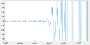
The above image is the begining of the wave of a song,I use halfband fir to interplote the wav,but the interploted wav is not good,how to interplote the wav to good status? the begining of the wave is just noise,I want to filter it out .
Last edited:
Almost all of this discussion is well above my head.
My reason for writing is my admiration for Russian audio designers. There is an insight into perception that I think the Russian mind understands better than any other. Funny from a people who were once led by folks who thought they could change human behaviour.
I liked the way ska wrote from the first and when he said he was educated in Russia/Soviet Russia I nodded to myself that - yet again great good sense and innovation with an understanding of the goodness of simplicity over complication. A trend I notice almost without fail in Russian practitioners of audio arts and science.
Ska, if you make these I would love to be able to buy and hear what you have wrought.
There is an attachment to the post at: https://www.diyaudio.com/community/threads/general-purpose-dac-clock-board.413001/post-7709201 which explains the various ways to measure phase noise and their limitation. For close-in phase noise, it shows up in FFT spectral line noise skirts (also AM noise from Vref constitutes part of the skirt noise). OTOH, far-out phase noise shows up in the overall noise floor. However, a quantitative measure of phase noise usually is limited to measuring at the clock/oscillator using something like a Time Pod instrument.Understood, looks like the skirts on FFT are not relevant to the clock jitter at all.
To measure oscillator jitter/p-noise correctly,
you need to transfer the clock frequency to DC using the same oscillator as reference for RF mixer.
- Home
- Source & Line
- Digital Line Level
- Discrete FPGA DAC project