Nelson, is this the circuit of post #78 with 2sa1016/2sc2363 throughout or input diff stage only?
Rüdiger
Rüdiger
The amp with bipolar CFP input stage turned out to sound really beatiful. Warm and detailed. Smooth and laid back compared to the JFET input amps. Again it's the details such as room information/reverb effects that improved, and everything sounds cleaner. It measures well in RMAA and looks OK on the scope.
Left fft is E-mu 1212M loop-back and right is this amp with 33R load. On the scope it's 100 kHz, 1V, 33R load.
Those plots look good, glad you're happy after all that work.
I use SA1016/SC2362 throughout - input stage, VAS, current mirrors, shunt transistor and the input of the diamond buffer. I love the warm yet detailed sound they produce.Nelson, is this the circuit of post #78 with 2sa1016/2sc2363 throughout or input diff stage only?
Rüdiger
I added charge suckout capacitors to the output stage not shown in the schematic.
I didn't take time to balance the currents through T1 vs the VAS and used diodes instead of R8, so the CM collector voltages aren't balanced. I haven't (yet) tried to go from shunt transistor emitter to the DB because I'm not sure if I'm willing to sacrifice any voltage swing. This amp usually run on batteries.
Low impedance voltage reference to the VAS and better output transistors are on my wish list.
Next in line to be '797-ized is the one with JFET/bipolar CFP input stage. I've run out of JFET's so it has to wait.
I did two more of these. This time I balanced the CM collector voltages as suggested by Samuel.
The one with standard bipolar input sounds as expected - like the bipolar CFP only not quite as good.
The JFET/bipolar CFP is a bit disappointing, because it was my favourite before adding the floating CM and shunt transistor. Now it's on the bright side. This is the only amp where I don't use SA1016/SC2362 everywhere. I had to use SC2240 as shunt transistors. I wonder if it could have such an impact. I have to try to find some SC2362's.
Is it a good idea to use a cap from the bases of the folded cascode transistors to positive rail or ground? Something like 10 nF. It simulates better, especially at unity gain (the ground channels in my amps are unity gain).
Attachments

I sacrificed some SC2362 from another project. Now the amp sounds like I expected from the AD797-izing it. It still is brighter than the bipolar version, but not as edgy. Those Toshiba transistors aren't to my taste.I wonder if it could have such an impact.
Even my favourite opamp based amp with OPA827 (and sometimes AD797) and OPA627 as ground put these to shame. Before adding the floating CM and shunt transistor, OPA827/627 had a better soundstage and was overall cleaner.
I couldn't get over the bright coloration of the version with CFP/bipolar input stage so I went back to using diodes to drop some voltage over the CM. Now it sounds as warm and beatiful as the one with bipolar CFP.
I'm confused with which components you are swapping and to which schematic you attribute the different sounds.
When I come home from work I'll show the up-to-date schematics.I'm confused with which components you are swapping and to which schematic you attribute the different sounds.
In short it seems like balancing the CM collector voltages by using a small resistor on the T1 emitter instead of a diode make the amp sound erroneous - too bright - and there's an "undershoot" in the square wave. Like stated earlier in this thread, the CM probably needs a little more voltage to operate properly.
Using a SC2240 instead of SC2362 as T1 (shunt) transistor makes the amp sound worse. I've come to the same conlusion when I've used SA970/SC2240 as input stage or VAS in this and other amps.
TzeYang, I'll do a summary after some more listening. I have five of these amps with different input stages: bipolar, JFET, JFET/bipolar CFP, bipolar/bipolar CFP, JFET/JFET cascode. I also have two un-'797-ized, one with JFET and one with bipolar input stage.
the 970/2240 is lower noise but I doubt that is what you are hearing.Using a SC2240 instead of SC2362 as T1 (shunt) transistor makes the amp sound worse. I've come to the same conclusion when I've used SA970/SC2240 as input stage or VAS in this and other amps.
The next difference could be different gain, but both are available in similar gains.
The biggest difference I can spot is Cob. The 2362 is much lower Cob than the 2240.
Anybody want to offer an opinion on why these sound different?
The CM probably needs a little more voltage to operate properly.
The problem is very likely not the output voltage of the current mirror per se but the current source which feeds it. With the 2SK170-based version you show the CCS is half-way saturated during most of the negative voltage swing. Because of that its output current is dynamically reduced, which again dynamically reduces the collector current of the emitter follower. This is seen as prelonged recovery from slewing and likely causes additional distortion which you might hear. A BJT current source would work *much* better.
I don't want to talk you into another revision--if you're happy with it don't touch it. However I feel that it's important to not attribute issues to the wrong source...
Samuel
which are you referring to J3, or J4, or J5, or J7?The problem is .....the current source which feeds it. With the 2SK170-based version you show the CCS is half-way
J7 could be a gr 170 without the 39r and then cascode it with a bf244b. Or is there a reason this two component arrangement would not work well?
In these small amps it's quite impossible to fit a BJT CCS. I used JFETs to make it pocketable. Your input is welcome, and if I make a speaker amp based on this circuit I'll bear this in mind. I'm not so clever with electronics, and I don't understand the saturation issue. Could you explain it so a noob like me can understand it? In reality there's no resistor from source to ground on the J7 JFET. I picked samples with appropriate IDSS.The problem is very likely not the output voltage of the current mirror per se but the current source which feeds it. With the 2SK170-based version you show the CCS is half-way saturated during most of the negative voltage swing. Because of that its output current is dynamically reduced, which again dynamically reduces the collector current of the emitter follower. This is seen as prelonged recovery from slewing and likely causes additional distortion which you might hear. A BJT current source would work *much* better.
I don't want to talk you into another revision--if you're happy with it don't touch it. However I feel that it's important to not attribute issues to the wrong source...
Samuel
In one of my versions I used 2N5486 as J7 (CCS to the floating CM), and the distortion was bad at higher levels. I wonder if this is effect of saturation. Quite unacceptable, so I changed it to a bipolar CCS and a a small resistor on the T1 emitter with the result of balanced CM collector voltages as per Samuels suggestions. This amp measures better than any other. I guiess you were right Samuel. I haven't listened to it yet.
Attachments

In real life I do. I use SK170GR and they vary between 2 and 7 mA. The Spice models have 12.5 mA IDSS.150 ohm for RK and RL seems high. You could use a lower IDSS part and lower the R.
I don't understand the saturation issue.
Every CCS needs some voltage to work with; once the collector/drain gets close enough to the emitter/source the according transistor approaches saturation, i.e. it stops working as a transistor so to speak. In a CCS this results in reduced output current--in this saturation region it doesn't behave like a CCS but more like a resistor. For your 2SK170 CCS this will happen for voltages below 3-4 V; with 5 V supply rails there's not much room left.
More on this (though mostly for BJTs) here: www.designinganalogchips.com/_count/designinganalogchips.pdf
See page 75ff.
Samuel
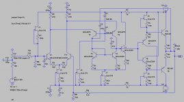
I felt challenged by the design problem of implementing the AD797 topology for +/-5 V rails, relatively low quiescent current and reasonable complexity. So I sketched an amplifier which is what I'd start with: JFET-AD797_r1.pdf
As shown the amplifier provides an output voltage of almost 8 Vpp into 100 Ohm with very low distortion. This is achieved by careful design of the biasing elements and the use of boostrapped resistor loads instead of CCSs in the output stage. Pulse response is clean without significant overshoot.
Note that I've not tried this in real world, although I believe it should work well as shown. Possibly C7 might need to be increased somewhat if stability is an issue. Also the quiescent conditions will likely need some adjustment (by altering R4, R7, R8 and R12) to achieve the nominal values as shown in the schematic. R15/R16 should be selected for desired output stage quiescent current. R3 trims voltage offset.
Samuel
5V rails is tough for any CCS, and I can't see that an LED-BJT type would be any better. I would guess worse as it loses 2V for the voltage reference (and wastes current). Capacitor bootstrapping the drivers as in Samuel's example is a good one to try.
2 transistor feedback ccs works down to <1 V on output
matched bjt current mirror output is still within 1% at <0.5 V - then you have 5-10 V on the other leg to make a ccs
at least at mA currents where the forward bias of the output bc junction isn't leaking too much
I completely agree that RC bootstrapping can be a good solution but the C is physically large compared to the 2 bjt options above
Last edited:
- Status
- Not open for further replies.
- Home
- Amplifiers
- Solid State
- Discrete AD797 up and running