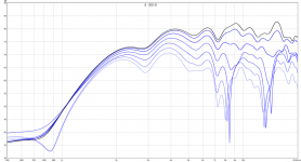
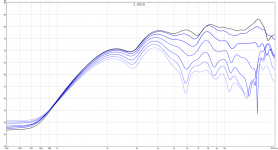
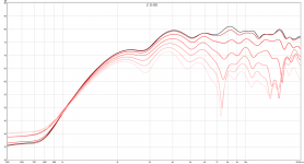
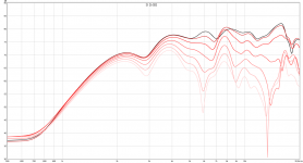
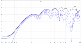
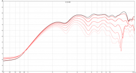
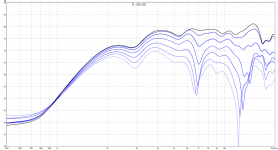
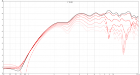
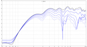
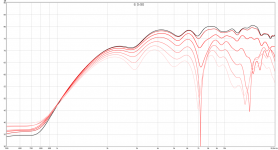
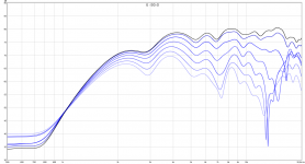
More graphs:
Attachments
-
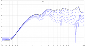 1 -90-0.png194.8 KB · Views: 668
 -
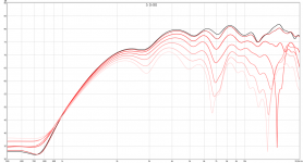 5 0-90.png193.5 KB · Views: 86
 -
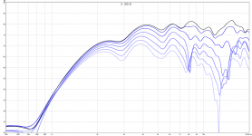 5 -90-0.png198.4 KB · Views: 85
 -
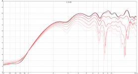 4 0-90.png195.8 KB · Views: 92
 -
 4 -90-0.png213.2 KB · Views: 96
 -
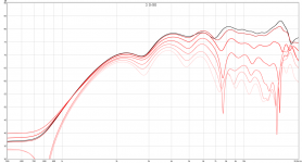 3 0-90.png198.6 KB · Views: 92
 -
 3 -90-0.png188 KB · Views: 598
 -
 2 0-90.png177.7 KB · Views: 620
 -
 2 -90-0.png185.2 KB · Views: 641
 -
 1 0-90.png186.7 KB · Views: 652
Some more progress, the back bowls on the waveguide is now done. They are finally painted too =)
I'll have to order some more wire but when that arrives I can mount the drivers on the other speaker too. And when my inductors and the second waveguide arrive I can assemble the other speaker too.
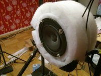
Then it's just to finalize the front wool sheet then to wrap it into black acoustically transparent fabric and then mount it with lots of velcro tape. The bottom of the speaker is to covered in purple upholstery fabric with some more velcro tape.
I'll have to order some more wire but when that arrives I can mount the drivers on the other speaker too. And when my inductors and the second waveguide arrive I can assemble the other speaker too.
Then it's just to finalize the front wool sheet then to wrap it into black acoustically transparent fabric and then mount it with lots of velcro tape. The bottom of the speaker is to covered in purple upholstery fabric with some more velcro tape.
Attachments
Does your circular baffle caveat hold true only if the driver(s) are centred on it?And here are Edge simulations about what effect the baffle makes to the same 170mm driver. Arrows indicate points of baffle effect treshold, dipole peak and dipole null.
My point is - any kind of acoustical baffle does these changes! This is because sound wave's path length to the edge of the baffle is what counts.
A wool felt sheet is just a little "weak" in this respect, it is virtually smaller than it's measured size. Likewise a thick baffle is virtually wider than it measures. "Wings or H edges add path length and break symmetry. A circular baffle is "worst case" because path lentgh is constant to the edge. A baffle with straight or oglique edges makes variations to path length - distributes and smooths out dipole peak and null. Wool felt makes paths a bit longer an diffuse too.
It seems to me an off centred driver on a circular baffle wouldn't have any common length sound paths to its baffle edge.
Been wrong before, of course. : )
Does your circular baffle caveat hold true only if the driver(s) are centred on it?
It seems to me an off centred driver on a circular baffle wouldn't have any common length sound paths to its baffle edge.
Been wrong before, of course. : )
That is true, that is one of the techniques to "hide" the dipole peak by spreading it out. It doesn't always work as nicely in practice though as the dipole peak problems are still there although somewhat hidden, best seen in the off axis repsonse. So in some direction we might have a null, but not in another. And even if the peaks are undesirable it is still kinda nice that they are predictable and thus possible to handle in the design.
But yes, if you use a hard baffle large enough that the dipole peaks are in the middle of the response then it is a very good idea to lessen the problem.
Another thing that has been suggested here but I haven't tried myself is if one uses a hard baffle as core but then cover it with absorptive material, it might be as good but as I haven't tried I don't know for sure =)
Here is a Edge simulation, 200mm diameter circular baffle, 100mm diameter circular driver in center an at edge. Dipole null is almost the same but ripples above it are very much nicer with offset driver. Gradient Helsinki usis this trick with their "cookie cardioid mid"
Attachments
Might be a bit late, but I think it's still worth mentioning.
For dipole with the assitance of absorbing material, this is one of the best example in my mind: http://www.diyaudio.com/forums/multi-way/153928-pioneer-pax-25b-coaxial-drivers.html#post2353574
It's a shame I can't find the original discusion for the full detail. The photo in the post above is the only one I can find now.
Keeping the LXmini example: treble roll off at 10k hz : can we have advantage to put fabric material on the driver as behind it but thicker to have a resistive load...
That is true, that is one of the techniques to "hide" the dipole peak by spreading it out. It doesn't always work as nicely in practice though as the dipole peak problems are still there although somewhat hidden, best seen in the off axis repsonse.
It's a good method if you incorporate solutions to reduce the peaking as well as to disperse it across various frequencies- the less coherent the peaking the less problematic.
Here is a Edge simulation, 200mm diameter circular baffle, 100mm diameter circular driver in center an at edge. Dipole null is almost the same but ripples above it are very much nicer with offset driver. Gradient Helsinki usis this trick with their "cookie cardioid mid"
Tried this on a tilted baffle: off centred Seas TV21, used as midrange.
Works well, added bonus- the break ups seem to disappear, as they're beamed overhead.
I just tried if wool can save you if you have a too big baffle:
The measurements are 0 - 90 ish, not exactly 15 degrees in between each measurement but somewhat close. And I guess the answer to the question is no, you cant =)
Why am I doing this? I'm moving into a less spacious place + I ideally want less ugly speakers and thus I'm considering minimizing my speaker: Split the subs into a multisub arrangement and then do the 100-150 hz and above in a simple 2 way by crossing to 2 waveguided tweeters. The tweeters have quite a bit of offset though so I wondered if it is possible to do the same but with a pair of 6.5" midwoofers or if the dipoleness will ruin everything.
I did measurements where both drivers were naked apart from wool and those measurements looked promising so I think I'll revert to that and do some more testing. I'm currently measuring indoors and I never get good 90 degree measurements when I do, so I might move the rig outside tomorrow to test naked & with some wool without some walls to ruin everything =)
The ideal is to then have the mids below the waveguided tweeters and then with wool baffles around them end up with 45-50 cm spheres I can suspend from the celing + cover the whole ball in acoustic fabric so they look better... I basically want it to look like a sphere lamp.
Attachments
After some more testing I conclude that it seems that back to back mounted midwoofers doesn't work above the bass region, and if you stay there you might as well just use a large hard baffle instead =)
I realized that the good measurements I got was when it was wired as a bipole, but I want a dipole and wired as such it is pretty awful.
The left measurement is the driver naked, and the right one with wool on the sides.
I realized that the good measurements I got was when it was wired as a bipole, but I want a dipole and wired as such it is pretty awful.
The left measurement is the driver naked, and the right one with wool on the sides.
Attachments
Had to bump.
Going to biltema to get some wool and try to do something to 400-2k area.
please update your current situation
Going to biltema to get some wool and try to do something to 400-2k area.
please update your current situation
I haven't had time to fiddle as I bought an apartment I decided to renovate so the speakers got pushed down in priority =)
Now it is time to look at them again...
I haven't found anything revolutionary since my last posts. Wool still works wonders and the plan for the speaker is to still use lots of wool. I will have a solid baffle just so I can mount the drivers but it will be minimal, all the rest will be a lossy wool baffle. Maybe in a month or two I will have the actual speaker ready to show off.
Hello, all.
I tried 2" thick foam around a midbass driver, formerly no baffle , extended bolt mounted- which goes up to 1500 hertz in this no baffle, soft baffle, U Frame bass bin setup.
It really smooths out this driver's sound, eliminating a previously unnoticed splashy quality at its upper range.
In rereading a contributor's statement that a driver centred in a round flat baffle may be the worst dipole arrangement, is any baffle more prone to "centred in a circular baffle" distortions than a nude round driver?
All distances from the acoustic centre must be identical , resulting in sharp peaks and valleys at wavelengths matching the drivers measurements from centre to frame, I'm guessing.
Thanks for the soft baffle inspiration!
Attachments
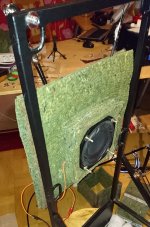
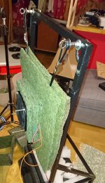
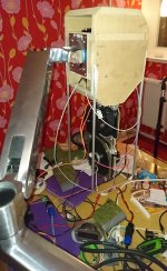
The last experiment. Wool not applied yet as I wanted to try if it worked fist.
And the result is: it doesn't work! The arm is nice it resonates at ~ 143 hz so would not work unless I could decouple it or arrange such that the speaker doesn't vibrate below say 300 hz. If i decouple it then it would be too large.
I've gone back to my original design, will hopefully have it assembled in a few days.
Attachments
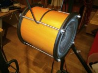
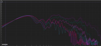
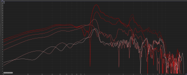
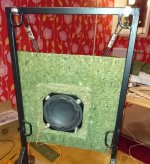
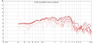
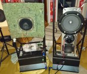
More data, but this time I have a success to talk about!
I built a pair of normal baffles (mids not mounted atm) but they are big, as big as the LX521 and ideally I want something smaller. They also have a box resonance at ~ 150 hz. In the perfect world I want it to have no panel vibrations so I'm continuing with experiments:
I've been looking at splitting the top and bottom, and swapping the 10" with two smaller drivers opposed in a force cancelling setup. The big problem is the midrange, I don't want a top-bottom setup but rather back to back so I get a perfectly symmetrical response and also so I don't have to listen to the rear of the drivers.
I've done lots of tries that failed miserably. The problem is that the rear driver influences the front making a null at about 700-900 hz at 0-30 degrees. The solution was to add more wool between the drivers such that this front to back interference is reduced. Lastly we have 0-90 -ish (I moved it by hand and not by exact steps) of the speaker in the picture. There is 1/12 oct smoothing.
I think it measures beautifully. Apart from a minor hiccup at ~ 750 - 850 hz it is almost perfect.. The idea is for them to cover 300 - 2400 hz. I'll try to make some minor tweaks and see if I can improve it further but even if I can't I'm happy with this.
After tweaking I'll start building a more permanent box, I'll then also add the woofers which will sit above and below the mids kinda like a W-frame but cut in the middle to make room for the mids.
Attachments
Interesting stuff. I do want to point out one thing. Adding heavy carpeting to the baffle will make some frequencies behave more like the driver is radiating into free space instead of half space with the baffle. This should influence the radiation pattern and also increase the rate of signal drop off per unit distance.
If it's uniform, then no problem. If it does this for different frequencies then you'll have more and more uneven levels as you get further away from the speaker.
Best,
Erik
If it's uniform, then no problem. If it does this for different frequencies then you'll have more and more uneven levels as you get further away from the speaker.
Best,
Erik
Interesting, I'll have to try that later when I can measure from a greater distance.
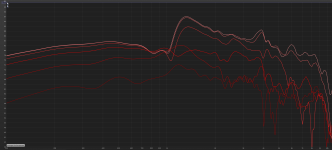
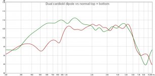
I have found the nail in the coffin for the dual cardioid setup: the efficiency loss, and by extension the added distortion caused by compensating for this loss.
Here is the dual cardioid vs a normal top bottom dipole fed with identical signals both at 1 m distance. I've also included the difference at the bottom. Over 10 dB lost from ~ 400 to 1000 hz. Even as high as 14 dB at 515 hz! 😱 I was prepared to trade 3-6 dB efficiency but I can't justify throwing away over 10 dB.
To make matters worse the top bottom speaker don't even have wool baffles, so it would probably be more sensitive at ~ 200 - 400 hz and crush the dual cardioid even more.
Back to the drawing board I guess 😉
Attachments
Last edited:
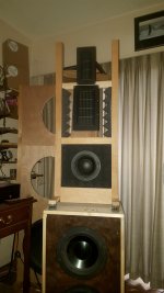
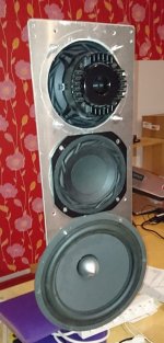
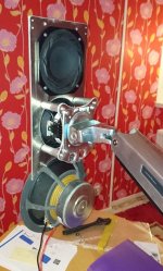
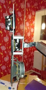
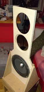
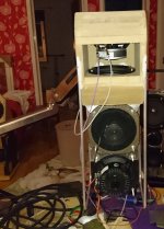
At last I have more progress!
Here is the next iteration, no wool applied yet but that is the next step. First I wanted to ensure that it performs well and without vibrating too much =)
And it seems to work well enough. The woofers are L16RN-SL and cover up to 300 hz where the 6ND430 takes over. The measured off-axis badness at 2-6 khz is from the tweeter and from previous experiments I know that a wool tunnel / waveguide around the tweeter will solve it.
It is a bit smaller than my previous massive experiments. With the arm there is pretty much no footprint either which is very nice.
And the reason for the tubing is because I want to cover the speaker in fabric. Naked drivers are not beautiful enough 😉
Attachments


Last edited:
- Status
- Not open for further replies.
- Home
- Loudspeakers
- Multi-Way
- Dipole wool carpet baffle experiment