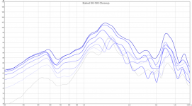
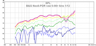
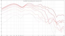
"the response is flawless up to 3 khz but above that there is ugly peaks in the off axis repsonse so the rear of this driver isn't usable full range.
That looks like dipole null around 3,5kHz and typical comb filtering above it. Below 3kHz you have typical constant directivity of a dipole at it's dipole range.
Dipoles and Open Baffles

The frequency of dipole peak and null is determined by the smallest diameter of baffle. Some of your early felt measurements "make dipole peak and null disappear" obviously because you measure at too close (considering the widened baffle). I was wondering of this earlier but your photo of measuring setup revealed that. Now, when you have eq'd response you will see the dirver loosing it's directivity at and above dipole null
One of other graphs shows dipole peak around 800Hz, the bigger driver obviously. Where are xos?
That is possible, the baffle was 42 cm wide though so if there was a dipole null it shouldn't it have appeared much lower in frequency?
In the first measurements though I measured outside form 1 m if I remember correctly. And what makes me believe that it's the rear response is this, I'm also suspicious that it is comb filtering from the two mids: In the end I might be wrong though and you right =)
I'll try to reproduce the best response until now which is single driver, tweeter in middle and single tweeter pointing backwards. I'll agument the low end of the back tweeter with a waveguide. If this shows the same problems up high as in the dual mid setup then I'll have to rethink it and look for new solutions, probably with smaller baffles.
And the XOs I've tested are acoustically in between 2-4 khz, 12-24 dB / oct in different test iterations. I can get 0-60 degrees almost perfect but If I do then at 75-90 the response is horrible with peaks and dips like in the picture. No matter what xo freq I tested I couldn't remove them and I didn't get close to the previously best response.
EDIT: Another reason of why I'm not convinced it's a normal dipole peak is that this is a 6.5 inch driver so it looses directivity 90 degree at 2 khz and this is 4-6 khz. Does the driver even have the directivity to cause the peaks and dips at 105-120 degrees? But for all I know it might =)
In the end it might be so that wool isn't suitable for letting one get away with bigger baffles but rather a way to increase efficiency in a system that already has small baffles.
Attachments
Last edited:
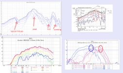
In the attachment are measurements of OllBoll, S Linkwitz and myself, all showing typical unequalized dipole response of circular cone drivers in narrow baffle.
I each one we can see directivity changes that appear near dipole peak, null and above it. Some measurements show also other issues.
All these contribute to made a dipole driver's workable "comfort zone" quite narrow.
Here is the suggested method of making a 4-way dipole speaker by Rudolf
I each one we can see directivity changes that appear near dipole peak, null and above it. Some measurements show also other issues.
All these contribute to made a dipole driver's workable "comfort zone" quite narrow.
Here is the suggested method of making a 4-way dipole speaker by Rudolf
Attachments
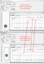
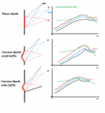
And here are Edge simulations about what effect the baffle makes to the same 170mm driver. Arrows indicate points of baffle effect treshold, dipole peak and dipole null.
My point is - any kind of acoustical baffle does these changes! This is because sound wave's path length to the edge of the baffle is what counts.
A wool felt sheet is just a little "weak" in this respect, it is virtually smaller than it's measured size. Likewise a thick baffle is virtually wider than it measures. "Wings or H edges add path length and break symmetry. A circular baffle is "worst case" because path lentgh is constant to the edge. A baffle with straight or oglique edges makes variations to path length - distributes and smooths out dipole peak and null. Wool felt makes paths a bit longer an diffuse too.
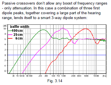
To sum this - when we want dipole action above 1kHz, the baffle must be less than 300mm narrow! If we want dipole action above 3kHz, baffle width must be less than 10cm!
ps. this is why I don't believe in dipole tweeters, they are physically impossible! Above dipole peak determined by width, they are bipoles and sum/null by lobing!
My point is - any kind of acoustical baffle does these changes! This is because sound wave's path length to the edge of the baffle is what counts.
A wool felt sheet is just a little "weak" in this respect, it is virtually smaller than it's measured size. Likewise a thick baffle is virtually wider than it measures. "Wings or H edges add path length and break symmetry. A circular baffle is "worst case" because path lentgh is constant to the edge. A baffle with straight or oglique edges makes variations to path length - distributes and smooths out dipole peak and null. Wool felt makes paths a bit longer an diffuse too.
To sum this - when we want dipole action above 1kHz, the baffle must be less than 300mm narrow! If we want dipole action above 3kHz, baffle width must be less than 10cm!
ps. this is why I don't believe in dipole tweeters, they are physically impossible! Above dipole peak determined by width, they are bipoles and sum/null by lobing!
Attachments
Last edited:
J Kreskowsky tells what happens when we rotate a dipole driver with some diameter (a plane in simulation, not a cone!)
By rotating, relative pathlengths change and the edge "shortens" and peak moves up. Also response below peak is reduced because of less radiating area!
This is true for planars, not for cones! Cones generate the excessive peak near dipole peak, because the radiating membrane is not planar!
And here is a planar B&G Neo8 off-axis measurement, it follows the theory presentd by JK!
By rotating, relative pathlengths change and the edge "shortens" and peak moves up. Also response below peak is reduced because of less radiating area!
This is true for planars, not for cones! Cones generate the excessive peak near dipole peak, because the radiating membrane is not planar!
An externally hosted image should be here but it was not working when we last tested it.
And here is a planar B&G Neo8 off-axis measurement, it follows the theory presentd by JK!
Attachments
And here are Edge simulations about what effect the baffle makes to the same 170mm driver. Arrows indicate points of baffle effect treshold, dipole peak and dipole null.
My point is - any kind of acoustical baffle does these changes! This is because sound wave's path length to the edge of the baffle is what counts.
A wool felt sheet is just a little "weak" in this respect, it is virtually smaller than it's measured size. Likewise a thick baffle is virtually wider than it measures. "Wings or H edges add path length and break symmetry. A circular baffle is "worst case" because path lentgh is constant to the edge. A baffle with straight or oglique edges makes variations to path length - distributes and smooths out dipole peak and null. Wool felt makes paths a bit longer an diffuse too.
To sum this - when we want dipole action above 1kHz, the baffle must be less than 300mm narrow! If we want dipole action above 3kHz, baffle width must be less than 10cm!
ps. this is why I don't believe in dipole tweeters, they are physically impossible! Above dipole peak determined by width, they are bipoles and sum/null by lobing!
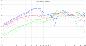
Yes, with normal baffles but there is still the case of naked driver vs naked driver with only wool baffle. Except for a tiny 1 dB glitch at 0 degrees @ 700-1200 hz they are almost the same, except that the wool baffle has far more efficiency at the lower frequencies. You get almost the efficiency of wood but none of the nulls from it.
EDIT: Uploaded the wrong naked graph =)
If in the end wool can't let you use drivers higher than you can when run naked there is one question that springs my mind. Say that you like Linkwitz, Rudolf and all the others have a complete dipole speaker with minimized baffles. It is probably a 4-way and very inefficient as it is. Would adding an extra wool baffle to this speaker give "free" efficiency without messing up the dipole response?
About dipole tweeters, with normal tweeters I agree with you but what if you choose tweeters that have narrow directivity? Say a compression tweeter with a horn such that there is almost no output @ 90-180 and therefore will only affect the opposite driver marginally.
Attachments
Last edited:
Hmm, I just thought of something.
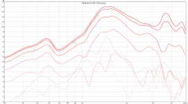
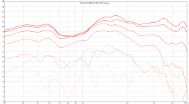
Currently I have the small wood baffles to help me mount the wool, when I measured the midrange without any baffle I didn't see the anomalies I did now... what if this small wood baffle is enough to create those anomalies? Maybe I should remove this baffle and run the drivers completely naked except for the wool before I call this design faulty.
Currently I have the small wood baffles to help me mount the wool, when I measured the midrange without any baffle I didn't see the anomalies I did now... what if this small wood baffle is enough to create those anomalies? Maybe I should remove this baffle and run the drivers completely naked except for the wool before I call this design faulty.
Added baffle area lifts low response and moves dipole peak down. This is why latest dipoles have narrowing baffles or are nudies. With a 4-way we can spread dipole function (= constant radiation pattern) to wider range.
I have come to see that it is practically impossible to make a loudspeaker that is dipole through it's passband! Every construction by JK, SL, Rudolf or me are defective!
However, when we speak of "open baffle" instead of "dipole" we semiotically accept this deficiency! Open baffles radiate as much energy front and back, but they don't null perfectly and don't have the figure 8 radiation pattern. However they do create a very unique acoustic field, more like omnis than monopoles. We must accept their nature and this imperfection of not being fully dipole.
A loudspeaker's power response comes from it's spectral SPL in 3Dimensions. Usually only horizontal off-axis is measured. Vertical off-axis is also very important and it may add good or bad things to power response.
When we listen to a speaker in a small room, it's direct radiation is more important than power response. This is why it is important to have smooth response in the "listening window" A dipole has higher direct/reflected ratio (D/R) than a monopole, which has higher than omni. A horn has highest D/R ratio. Directivity Index DI is measured in anechoid chambers, it is a feature of a speaker only. D/R ratio is measured in a room with reflecting boundaries.
The off-axis radiation should not have sharp changes, this is the key to smooth power response. When a speaker with inconsistent off-axis is eq'd straight on-axis, it's power response suffers!
Smooth polars is major goal in modern speaker design! Some old school speakers made it too!
Last edited:
"what if this small wood baffle is enough to create those anomalies?"
- obviously to some degree! It blocks/reflects bacwards radiation.
- obviously to some degree! It blocks/reflects bacwards radiation.
Interested to see the measurements for the wool-only baffle - challenge becomes mounting the drivers! The wood would make that easy, not so easy with wool only, methinks (unless hanging from a frame like you're doing). Do you think a baffle with ZERO overhang around the driver edges - i.e. just enough to mount them on - would still cause problems? Or is it the fact that the wooden baffle extends 3/4" or so around the driver edges?
Interested to see the measurements for the wool-only baffle - challenge becomes mounting the drivers! The wood would make that easy, not so easy with wool only, methinks (unless hanging from a frame like you're doing). Do you think a baffle with ZERO overhang around the driver edges - i.e. just enough to mount them on - would still cause problems? Or is it the fact that the wooden baffle extends 3/4" or so around the driver edges?
Those measurements are exactly that =)
I did a setup where the driver was held by the magnet so I could test how they measured. It looked like this:
Attachments

"what if this small wood baffle is enough to create those anomalies?"
- obviously to some degree! It blocks/reflects bacwards radiation.
I thought some more and If I have done this correctly this is 0 combined with 180, 15 combined with 165 and so on: the theroetically perfect response in the utopic case if you used dual opposite mids.
I think I'll remove the MDF baffle and see if the result approaches this or if it is just fantasy =)
EDIT: Or on second thought it's probably a fantasy since the sources are a distance D greater than the wavelength from each other. I guess better plots would be + and - bars to denote the scope of interference the rear driver can have on the front response when outside 1/X wavelengths.
Attachments
Last edited:
A perfect dipole radiator is a single point or plane with zero thickness. Then path length is same and summing at edges is perfect. Radiation to 90¤ off is zero.
A multipole is two or more radiators separated by distance, and therefore summing (phase match) occurs at random frequencies, leading to "lobing" In practise this is what happens after dipole peak in response! Dipole shifts to multipole.
A planar open back ribbon like BG Neo series is as close to theory as possible. Cone drivers and multidriver speakers will never be as good.
Dr. Dan Russel tells more..
Dan Russell's Acoustics and Vibration Animations
Pressure and Particle Displacement Upon Reflection
Sound Radiation from Dipoles and Quadrupoles - YouTube
Siegfried Linkwitz gives loads of info and links http://www.linkwitzlab.com/x-models.htm#Models
Last edited:
A planar open back ribbon like BG Neo series is as close to theory as possible. Cone drivers and multidriver speakers will never be as good.
Great explanation, thanks! Capitalizing on that notion...
Working on getting up the gumption to try building this as a studio monitor:
An externally hosted image should be here but it was not working when we last tested it.
Neo3, Neo10's, and GR Research servo woofers.
All-wool baffle, will probably try to magnet-mount drivers like you did in the photo you just posted.
Should I make the wool baffle bigger than this? Seems a little tight around the drivers, maybe, but don't have a good intuition around this kind of thing yet.
Also, OldBoll, you mentioned it doesn't take much thickness for the wool baffle to be effective - but is thicker badder? Would like to have a little bit of shape/rigidity to the baffle if possible. I'm thinking 1" thick wool or something.
Last edited:
dkmooers, your baffle width is the bottle neck, there will not be dipole summing above say 1000Hz. Another issue is horizontal offset of woofers - it will make interferences around xo (mainly dip in off-axis response), seriously if you use softer than LR8.
Preferably make a wide lower panel for woofers and a narrow or hourglass shape for Neo10 and Neo3.
Preferably make a wide lower panel for woofers and a narrow or hourglass shape for Neo10 and Neo3.
Also, OldBoll, you mentioned it doesn't take much thickness for the wool baffle to be effective - but is thicker badder? Would like to have a little bit of shape/rigidity to the baffle if possible. I'm thinking 1" thick wool or something.
I measured down to 100 hz and I coudln't see a significant difference when I added sheets so I stopped doing it. If you go lower then it will probably make a difference though, below 100 hz I use a solid MDF W-frame sub so I never felt compelled to investigate wool baffles in that region.
Juha,A perfect dipole radiator is a single point or plane with zero thickness. Then path length is same and summing at edges is perfect. Radiation to 90¤ off is zero.
A multipole is two or more radiators separated by distance, and therefore summing (phase match) occurs at random frequencies, leading to "lobing" In practise this is what happens after dipole peak in response! Dipole shifts to multipole.
isn't this highly misleading?
The "lobing" after the first dipole peak is a perfect "two source" behaviour. There is absolutely no reason to introduce multiple poles to explain it. None of your links is supporting that view.
Even if the sources become extended - circular moving pistons - , they basicly follow a dipole radiation pattern.
Rudolf
"Dipole shifts to multipole"
Yes, that is not scientifically true, but I think that is what is actually happening, as the result. Too much off-axis --> phase match is missed, resulting in lobing. A monopole just loses spl but since there is no backwave in antiphase, there is no lobing.
I made a freehand illustration about this. Response at 0¤ 30¤ and 60¤ I can not do the mathematics, sorry. A cone's diameter and depth determine it's peculiarity "Fp" (difference from planar source, see Klippel papers) This is based on analyzing actual measurements by me and many others.
Attachments
Last edited:
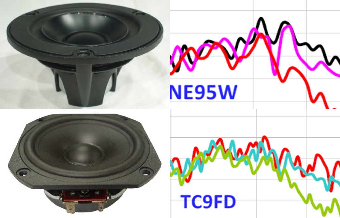
Are you referring to this:A cone's diameter and depth determine it's peculiarity "Fp" (difference from planar source, see Klippel papers)

If I use the formula for Fc for my midrange driver with 1,5 cm cone depth (H), I get Fc=7215 Hz. This is far from the frequencies you discuss in post #102 and 103. 🙄 It would need very deep and steep midrange cones to get Fc into the range discussed here.
Rudolf, I guess that depth is not th actual but virtual determined by cone angle. My VifaNE95 cones are very steep and aluminium. Some other versions of NE line have deep/steep cones too and they exhibit raggedness at certain Fc. Also most stiff cones (alu, Mg) show this more clearly than paper cones. This is because soft cones start to flex, and that´s why their upper response is "softer" generally
A driver I have been following too is SB Satori MW16 and it has a curved and deep cone. The response curves look familiar too (see 1,3kHz!), I think I know how it would measure as dipole!


A driver I have been following too is SB Satori MW16 and it has a curved and deep cone. The response curves look familiar too (see 1,3kHz!), I think I know how it would measure as dipole!
Last edited:
- Status
- Not open for further replies.
- Home
- Loudspeakers
- Multi-Way
- Dipole wool carpet baffle experiment