

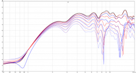
So much fiddling... except for one problem everything seems to go in the right direction though:
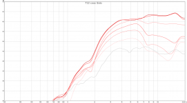
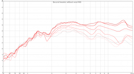
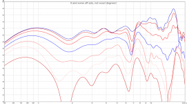
This result would be awesome if not for the glitch at 4-7 khz. The wierd thing is when I look at the tweeter response.
Thats the response of only the front tweeter, no mid and no back tweeter. The off axis response is totally messed up. I'm considering testing with another tweeter to ensure that it isn't the tweeter itself that is faulty. Tested with a wool waveguide and still the same 4-7 khz off axis peak.
If that off axis peak would get resolved I would have almost perfect front dispersion, then I'll just have to try to insert the rear tweeter but as it has a large waveguide it doesn't affect the front dispersion much so will probably not be too difficult.
EDIT:
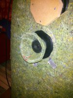
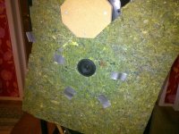
In case anyone wonders how a wool waveguide looks, here it is: =)
This result would be awesome if not for the glitch at 4-7 khz. The wierd thing is when I look at the tweeter response.
Thats the response of only the front tweeter, no mid and no back tweeter. The off axis response is totally messed up. I'm considering testing with another tweeter to ensure that it isn't the tweeter itself that is faulty. Tested with a wool waveguide and still the same 4-7 khz off axis peak.
If that off axis peak would get resolved I would have almost perfect front dispersion, then I'll just have to try to insert the rear tweeter but as it has a large waveguide it doesn't affect the front dispersion much so will probably not be too difficult.
EDIT:
In case anyone wonders how a wool waveguide looks, here it is: =)
Attachments

Last edited:
YYYYYYYYAAAAAAAAAYYYYYYYY!!!!!!!!!
I think I will discard the last tweeter:
This shoulnd't be that hard to integrate =)
Now I just got to test without the wool waveguide to see the difference, who knows... wool might be awesome for tweeter waveguides =)
I think I will discard the last tweeter:
This shoulnd't be that hard to integrate =)
Now I just got to test without the wool waveguide to see the difference, who knows... wool might be awesome for tweeter waveguides =)
Attachments
Now this is getting somewhere!
I can probably improve it further in the 2-4 khz range by crossing the tweeter lower and the midrange higher, I think it will smoothe the off axis response.
If that doesn't work though this is probably good as is as long as I lightly use some global EQ to flatten the curve.
And as a bonus for me, this is without any delay on the tweeter =)
Attachments
Last edited:
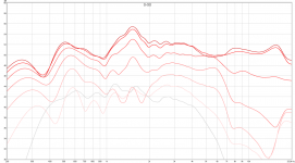
This is a 0-90 result I can live with. Apart from the actual crossovers the only EQ I have used is a negative gain high shelf and a small 1.3 Q notch =)
Next I'll fiddle with the rear tweeter and try to make the rear response not bad, after that it's probably time to start thinking about transferring the crossover sloppes to passive components.
Next I'll fiddle with the rear tweeter and try to make the rear response not bad, after that it's probably time to start thinking about transferring the crossover sloppes to passive components.
Attachments

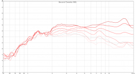
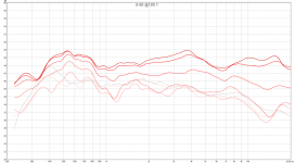
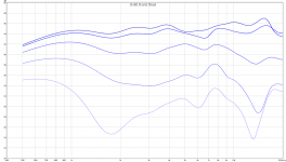
I say those results are pretty good, especially nice that there is consistently lower level at 75-105, no big dips or peaks =)
0-180 with the midrange, diy coaxial and then the waveguided tweeter firing backwards.
Mid / Coax tweet is crossed at about 12 dB oct at 3 khz with some overlap. Rear tweeter is crossed with mid at about 1.5 khz.
EDIT: Ignore below ~ 500 since I'm measuring indoors.
0-180 with the midrange, diy coaxial and then the waveguided tweeter firing backwards.
Mid / Coax tweet is crossed at about 12 dB oct at 3 khz with some overlap. Rear tweeter is crossed with mid at about 1.5 khz.
EDIT: Ignore below ~ 500 since I'm measuring indoors.
Attachments
Last edited:

I have decided to let this be as good as it gets for the front DIY coaxial:
I've measured 0-60 on the midrange with and without crossover ( 1st order BW @ 2400 hz ) and the same with tweeter ( LR2 @ 2400 hz ). I've also done impedance measurements on them. Acoustically the crossover is ~ LR2 at 2800 hz.
Next I had planned to import them into speaker workshop and then calculate me a crossover that turns the respective naked responses into the xovered responses. Because of Murphys law, however, I of course get a crash when I import the impedance so I'll have to solve that first.
I'm planning to make a series crossover since then I won't have to simulate the crossover as a unit but can keep the crossovers separate for each driver and then just combine them in the real world.
Attachments
Last edited:
What are measurement conditions? Distance? Windowing/gating/smoothing?
As presented plots look good, but lack detail.
As presented plots look good, but lack detail.
What are measurement conditions? Distance? Windowing/gating/smoothing?
As presented plots look good, but lack detail.
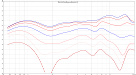
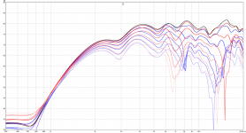
Measurement conditions are indoors sadly since it's too cold outside : /
Distance is 1.2 m, 2 ms gating and the closest reflection should be outside that scope.
Smoothing is 1/3 on the last measurements.
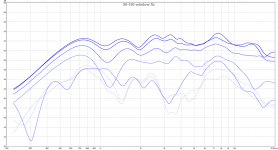
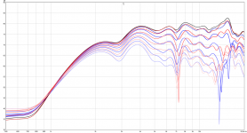
Here is some without smoothing:
You see a glitch at 15 degrees @ ~ 7 khz I'm not sure is measurement error or something in the speaker I can fix. It's not that bad though so I might just leave it since it is narrow and only in one of them.
Attachments

Thanks,
Much more of what is expected. 2ms gating is very limiting, but using this it is possible to take measurements from much further back where driver integration is much better.
It likely sounds much better than it looks.
Enjoy the adventure.
Much more of what is expected. 2ms gating is very limiting, but using this it is possible to take measurements from much further back where driver integration is much better.
It likely sounds much better than it looks.
Enjoy the adventure.
2dB separation between lines makes graphics look worse than they are. Generally we a used to looking at 5 or 10dB7/line. I checked my own measurements with 2ms, 6ms and 12ms gating, measured at roughly 1,2m. I often look at 9, 20 ,60ms too. I think 6 or 9ms are reliable for indoor, above 500Hz. Below that we are on weak ice always.
The 6-7kHz dip must be cavity effect with your coaxial arrangement, or said in another way, because the tweeter has no baffle except it's own circular body.
Other that that response regularity is fine! The felt cone for tweeter made cavity effects that were bad.
Driver xo match and delay/phase match should be checked with reversed-polarity method. Good match reduces off-axis ripples very efficiently, and is very important to get "clarity and good transients" from the system.
2dB separation between lines makes graphics look worse than they are. Generally we a used to looking at 5 or 10dB7/line. I checked my own measurements with 2ms, 6ms and 12ms gating, measured at roughly 1,2m. I often look at 9, 20 ,60ms too. I think 6 or 9ms are reliable for indoor, above 500Hz. Below that we are on weak ice always.
The 6-7kHz dip must be cavity effect with your coaxial arrangement, or said in another way, because the tweeter has no baffle except it's own circular body.
Other that that response regularity is fine! The felt cone for tweeter made cavity effects that were bad.
Driver xo match and delay/phase match should be checked with reversed-polarity method. Good match reduces off-axis ripples very efficiently, and is very important to get "clarity and good transients" from the system.
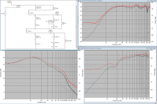
Yup, all in all I'm quite satisfied. If I inverse the tweeter there is a huge null so phase of tweeter and mid seems to be matched well, at least 0-45, there is a small dip at 60-75 but that's ok.
And I think I'll build this crossover, the 8 ohm in series is to simulate my future amp which has 8 ohm output impedance. The red curves are the acoustical curves of the drivers solo after DSP crossovers, and ofc the black ones are ones without DSP crossovers but with the simulated passive crossover.
Attachments
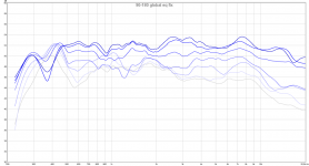
Hmm, just did something interesting:
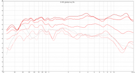
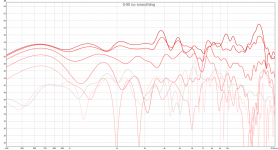
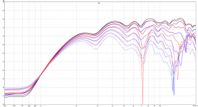
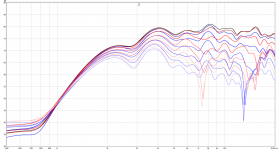
I read some more in the coaxial thread that some manifacturer used a baffle for the tweeter that the midrange could pass through, but not tweeter frequencies so I tried this:
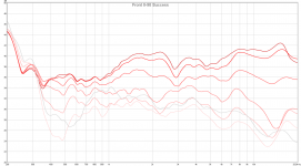
This is without smoothing ( NOT exact 15 degree measurements but about 0-75 from top to bottom ), so apart from the 6.8 khz dip and 7.6 khz peak it's almost perfect. I'll have to investigate if this is something inherent in the driver, or maybe just the one I'm using now ( I have 9 in total but will only use 4, so I can affoard to discard some and just pick the best ). If we apply 1/3 smoothing we can make it look much more nice =)
I only lost about a dB on midrange efficiency below 1 khz and a bit more 1-3 khz I could probably compensate by removing the first order lowpass in the 1-3 khz region. 1 dB efficiency loss below 1 khz would be a small cost for the smoothness in this graph though.
I read some more in the coaxial thread that some manifacturer used a baffle for the tweeter that the midrange could pass through, but not tweeter frequencies so I tried this:
This is without smoothing ( NOT exact 15 degree measurements but about 0-75 from top to bottom ), so apart from the 6.8 khz dip and 7.6 khz peak it's almost perfect. I'll have to investigate if this is something inherent in the driver, or maybe just the one I'm using now ( I have 9 in total but will only use 4, so I can affoard to discard some and just pick the best ). If we apply 1/3 smoothing we can make it look much more nice =)
I only lost about a dB on midrange efficiency below 1 khz and a bit more 1-3 khz I could probably compensate by removing the first order lowpass in the 1-3 khz region. 1 dB efficiency loss below 1 khz would be a small cost for the smoothness in this graph though.
Attachments
Last edited:
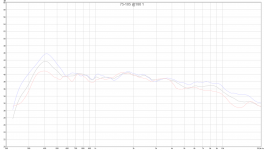
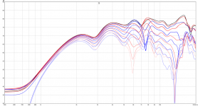
I just did some close mic measurements on the current tweeter and another one... the other one didn't have the 6.9 khz dip and 7.6 khz dip. There seems to be large variances in the tweeters so it is possible that I might have a tweeter or more that doesn't have such peaks or dips.
My current idea is to build myself a speakon -> alligator clips adapter and then make a test baffle for the tweeters. Then I'll test and do polars of all 9 and pick the 2 best as front tweeters, and the 2 best after that as rear tweeters.
Would be nice if I could get an unsmoothed response like the first of the measurements in the last post but without the narrow band peak + dip =)
I kind of think that using foam around a tweeter can be tricky ... probably similar with felt. I use a heil and depending on where foam/felt strips are placed on that unit, frequency response varies. Short story is that while it might improve one area of bandwidth it negatively affects another.
I kind of think that using foam around a tweeter can be tricky ... probably similar with felt. I use a heil and depending on where foam/felt strips are placed on that unit, frequency response varies. Short story is that while it might improve one area of bandwidth it negatively affects another.
If you profile it so as to keep the angle of incidence high, it helps a lot- For a horn, you want the foam to look like a continuation of the profile around the mouth, for example. With domes tapering foam or felt as it gets close to the diaphragm is very helpful, so that there's nothing immediately next to the 'phragm, then progressively more thickness.
This arrangement allows attenuation of the wavefront before it encounters the "meat" of the barrier, as well as acting as a smoother "hard" surface for frequencies at which the material is reflective.
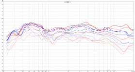
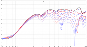
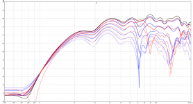
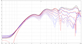
Moar data!
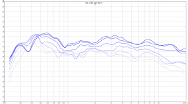
As we can see there are variations in the tweeters.
3 Was the first one I discarded and 9 the last one with the bigger null off axis.
All in all there will not be a perfect response, this is a 2 inch cone tweeter so above 5-6 khz they are probably somewhat unreliable.
In the end I think I'll choose 1 and 2 for my two front drivers, they are mostly the same so I can EQ a small 6-8 khz dip to make it more flat. In the end it will not be flat, probably at least one dip, but there won't be any sharp peaks so ought to be good enough.
Attachments
- Status
- Not open for further replies.
- Home
- Loudspeakers
- Multi-Way
- Dipole wool carpet baffle experiment