The 2N5088 is a small signal NPN device. My old Towers book says 2N3904 or BC349C but tbh I think pretty much any common current device would be OK.
Watch the pin outs on replacements, I haven't looked to see if they are the same.
The 2N5087 is PNP and 50 volt rated. Perhaps a BC557C for that.
No idea on the D40. Is it old? Was there ever a 2SD40 I wonder. Some of the devices around that number were actually Germaniums.
Could the last one be a TIP41? which is a common power transistor. The TIP41C is the highest voltage rating and the TIP41 the lowest.
The 2N5088 is a small signal NPN device. My old Towers book says 2N3904 or BC349C but tbh I think pretty much any common current device would be OK.
Great - I will have a look
Watch the pin outs on replacements, I haven't looked to see if they are the same.
The 2N5087 is PNP and 50 volt rated. Perhaps a BC557C for that.
Thanks
No idea on the D40. Is it old? Was there ever a 2SD40 I wonder. Some of the devices around that number were actually Germaniums.
This is a Darlington - found this but no idea where to source
D40K1 Datasheet PDF - Datasheet4U.com
Could the last one be a TIP41? which is a common power transistor. The TIP41C is the highest voltage rating and the TIP41 the lowest.
yeah TIP41/ thanks
There are lots of Darlingtons that should be suitable electrically but none in that package.
Look at the BD681G, the TIP122 and BD677.
Look at the BD681G, the TIP122 and BD677.
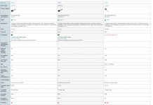
They are all fairly similar, the 2N3904 does have a 40 volt collector/emitter rating vs 30v for the others.
Never go lower on voltage than the original unless you can determine yourself that it will never see voltages approaching its limits. For example if the circuit operates on 20 volts then any would be fine, if it operates on 30 or 40 volts then you would need to study the circuit to see what the device will actual see in use in all conditions.
Same applies to collector current.
ft or transition frequency is the frequency where the small signal current gain falls to 1. For audio figures like 100MHz or 300MHz are so much higher than anything we encounter that it doesn't really make much difference, and the circuit itself should be designed to reign in any unwanted behaviour caused by transistor variations.
hFE is current gain and varies wildly between even devices of the same number. All circuits we encounter should work with values over a huge range... the beauty of negative feedback... it irons all these differences out.
Power dissipation is important and can vary a lot between devices of the same package. Again, unless you know or can calculate the power it will actually dissipate then don't go lower in a replacement.
so for collector current and collector voltage the number quoted are the limits that they can take? so if it's higher then there is a greater margin for failure?
In basic terms yes 🙂
If a transistor is rated 40 volts Vce then it can withstand that across it. Any higher risks failure. Normally a circuit has a good safety margin and would use for example a 40 volt device for voltages across the transistor of say no more than 30 volt.
Collector current is an absolute as well not to be exceeded.
Power is voltage across the transistor multiplied by current flowing through it and so you can see straight away that you can never have say 30 volts across the device and also its maximum current flowing at the same time.
30 volts * 0.5 amp would be 15 watts. And the device might be rated at 650 milliwatts maximum.
If it was switching a load such as a relay or bulb then you could have 30 volts * no current... so no power dissipation or you could have the transistor fully on (so it might have say 80 mv across it) and a current of 0.5 amp flowing. 0.08*0.5 is just 40 milliwatts and so all good.
Maybe 🙂
Looking at data sheets for these and they do seem to be quite high gain.
Langrex have been going for decades so might be worth a try.
Looking at data sheets for these and they do seem to be quite high gain.
Langrex have been going for decades so might be worth a try.
Well we have other options for running the LED.
If you want the LED to work the other way around then we can use pin 3 (that seems to be unused in the circuit) to run the LED.
If the led (and its series 10k resistor) is connected from pin 3 to ground then the LED is on at first (as now).
If the LED is connected from the 14v to pin 3 then the LED is off until the timer operates and then it will come on.
Just put in a Tant 33uF and 2.2M on R65 and I only get 1m 26s, what could I change to make it a bit longer on the resistance?
This was measuring Pin3 which goes from 14v to virtually zero mV 🙂
ahh //// just properly read the reply...ooops should have got a 47uF Tant. what would happen if I put the old 33uF electrolytic in parallel with this 33 uF Tant I wonder?
33uF and 2.2meg would give around what you are getting. Have a look at post #28
The simulation gives about 80 seconds delay for 33uF/2.2meg so its in the right ballpark. You can go higher with the resistor. A 3.3 meg would stretch that to around 2 minutes and a 3.9meg to around 2min 20s
The simulation gives about 80 seconds delay for 33uF/2.2meg so its in the right ballpark. You can go higher with the resistor. A 3.3 meg would stretch that to around 2 minutes and a 3.9meg to around 2min 20s
I have the LED positive from pin 3 and a 10k, but not sure where to take the -ve of the LED, just straight to ground or pin 1.
After the 10k it still measures 14v, presume this ok - sorry for so many dumb questions!!
After the 10k it still measures 14v, presume this ok - sorry for so many dumb questions!!
You can take it to the most convenient point, pin 1, the chassis, anywhere that is electrically connected to the same zero volts line.
You will measure the same voltage going in to a resistor as coming out, the resistor limits the current and not voltage.
Even a 100 million million ohm resistor would still have 14 volts at each end but your meter would not be able to measure that because the meter itself would be trying to draw current between the test probes. A typical DVM as a sensitivity of 10Meg ohm per volt.
Voltmeter Impact on Measured Circuit | DC Metering Circuits | Electronics Textbook
Try it with some of your 1 and 2 meg resistors. You will find the voltage isn't quite 14 volts. That is because of the meters own internal resistance loading it down.
- Home
- Design & Build
- Parts
- Diodes, LEDs and Optocouplers