That looks like a 750k.
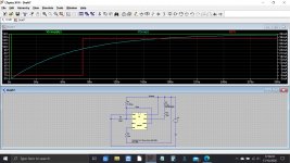
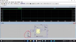
I through this together so you can see how it works. The supply appears 2 seconds into the simulation (bottom scale) and you can see the supply voltage and the voltage across the cap as it charges. When that voltages reaches around 2/3 of the supply voltage the 555 changes state and power the LED. LED current on right hand scale.
I through this together so you can see how it works. The supply appears 2 seconds into the simulation (bottom scale) and you can see the supply voltage and the voltage across the cap as it charges. When that voltages reaches around 2/3 of the supply voltage the 555 changes state and power the LED. LED current on right hand scale.
Attachments
WOW that's amazing, and very impressive - thanks
So I did take the mute off and it does create a voltage of 14V, so I will need to try a resistor that gives more like 2 mins, and also find a way of the mute not interrupting the voltage so I can have a light that is on when the amp is 'ready' and stabilised at 2mins.
maybe around 3M resistor as a guess?
I will have a look at the mute cable connection on the operate and maybe I can just unsolder that jumper?
If I put an LED in and give it 14V will it go pop!
THANKS!!
or 2 of these in series?
https://uk.farnell.com/dialight/521-9183f/led-red-t-1-3-4-5mm-8mcd-635nm/dp/1126055
https://uk.farnell.com/dialight/521-9183f/led-red-t-1-3-4-5mm-8mcd-635nm/dp/1126055
so here's a thought if this is logical.
If I connect the timer circuit to the other side of the switch, so that it gives 14V when the mute is ON, then when I start the amp, with the mute ON the timer will warm up and the light will appear after 2mins or when it's set and then when the operate is switched to listen to music it will go off again, and only reappear when the mute is selected?
Just an idea 🙂 as I can of course just run the timer to earth and let the light stay on?
Good 'innit 🙂
So, LED's are current driven, not voltage. It's a subtle difference.
If you ramp the voltage up across a red LED then no current will flow until you reach around 1.7 volts at which point current increases dramatically. A few millivolts increase changes the current massively.
14v = POP big time 😀
The LED needs to have a series resistor which in your circuit is the 300 ohm, however that value is to low and to much current will flow. It would be OK for a quick test with an old LED but if you are fitting something new and modern then change the 300ohm to say a 10k. The LED will still be very bright with that.
You don't have to fit two LED's if you only want one visible light.
If Q3 is being turned on then just removing the diode that feeds its base will stop it turning on.
There is a limit to how high a value resistor you can use. The currents are so small that leakage current in the cap can dominate plus the current taken by chip input that the cap connects to. That timing cap really does need to be a tantalum type.
A 2.2meg resistor and 47uF cap gets you close to two minutes delay.
Attachments
so here's a thought if this is logical.
If I connect the timer circuit to the other side of the switch, so that it gives 14V when the mute is ON, then when I start the amp, with the mute ON the timer will warm up and the light will appear after 2mins or when it's set and then when the operate is switched to listen to music it will go off again, and only reappear when the mute is selected?
Just an idea 🙂 as I can of course just run the timer to earth and let the light stay on?
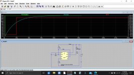
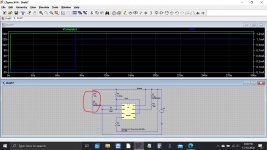
Well we have other options for running the LED.
If you want the LED to work the other way around then we can use pin 3 (that seems to be unused in the circuit) to run the LED.
If the led (and its series 10k resistor) is connected from pin 3 to ground then the LED is on at first (as now).
If the LED is connected from the 14v to pin 3 then the LED is off until the timer operates and then it will come on.
Attachments
ok - got it...I think.
So if I will use the existing green LED which I guess is old, and then remove Q3 or tap the point 45 in the circuit diagram to the other side of the switch as explained earlier so the light goes off when listening to music rather than 2 lights beaming out.....
I will swap the cap for a tant at 47 uF
I will put back a 2.2 Meg resistor in R65
I will swap R56 for 10k
done!!
🙂
Well we have other options for running the LED.
If you want the LED to work the other way around then we can use pin 3 (that seems to be unused in the circuit) to run the LED.
If the led (and its series 10k resistor) is connected from pin 3 to ground then the LED is on at first (as now).
If the LED is connected from the 14v to pin 3 then the LED is off until the timer operates and then it will come on.
just read this - even better light comes on to warn you of mute required and then drops off after 2mins warm up.....ooooh maybe even a flashing red one!!
Providing Q3 is OK then just lifting one end of D16 will effectively take it out of circuit.
The post I just did above these shows how to use pin 3 of the 555 timer to run an LED. Yu can have it either on or off when muted depending which way you connect it.
Have to leave it for tonight 🙂
This might help you understand the 555 timer which has been around for 40+ years... and still going strong.
NE555 TIMER
presume with the pin 3 option times switches it off
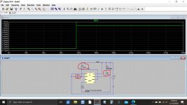
Pin 3 can both source and sink current, something pin 7 can not.
Look at the timing on the last two simulations and the LED connection and the LED current.
They are opposites.
One is on at first until the delay finishes, the other comes on after the delay finishes.
Bi Colour LED, Red to Green
Tomorrow

....he 555 timer which has been around for 40+ years... and still going strong....
Oral History Hans Camenzind 555
so I've ordered some stuff and will put this together and feedback 🙂
THANKS so much for the amazing support, Merry Christmas!!
Hey in another direction I have an intermittent problem and I think it might be a transistor failing / flopping at certain points, so I was just going to swap them BUT they are all no longer in production is there a good equivalent search / site anywhere?
🙂
Thanks 

Can't think of any sites that show equivalents although they probably exist somewhere. What is the transistor type number?
Can't think of any sites that show equivalents although they probably exist somewhere. What is the transistor type number?
- Home
- Design & Build
- Parts
- Diodes, LEDs and Optocouplers