Hello clever people, I am trying to understand the world of diodes, LEDs and optocouplers, so that I can find and understand equivalents.
I have a circuit that uses optocouplers and on the LED side I would like to match a no longer operational optocoupler with an LED so I can see the operation if this is possible. How do I unravel all of the specifications to be able to put in an LED that is electrically equivalent?
Thanks 🙂
This is the optocoupler http://www.farnell.com/datasheets/87223.pdf VLT5C1
 Thread moved.
If you just want to see when an opto couplers LED is active then either wire a standard LED in series with the opto one (only works if you have enough drive voltage and assumes the LED in the opto is not open circuit) or add a resistor and LED and limiting resistor in series from whatever drives the optos LED.
If you post the circuit with the opto we can tag in how to do it.
Any cheap red, yellow or green LED is OK to use.
If you post the circuit with the opto we can tag in how to do it.
Any cheap red, yellow or green LED is OK to use.
Optocouplers use infrared LEDs, so a LED salvaged from an old remote control is close.
Your smartphone camera can see the infrared
Your smartphone camera can see the infrared
If you just want to see when an opto couplers LED is active then either wire a standard LED in series with the opto one (only works if you have enough drive voltage and assumes the LED in the opto is not open circuit) or add a resistor and LED and limiting resistor in series from whatever drives the optos LED.
If you post the circuit with the opto we can tag in how to do it.
Any cheap red, yellow or green LED is OK to use.
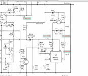
This is the circuit, I no longer have the optocouplers in circuit at all, and I wanted to replace with a diode or an LED, just to make sure some occasional instability is not due to this removal.
An LED would be useful to see the timing for me to activate the mute manually as this was part of a no longer operational auto mute circuit.
Attachments
Any LED will work in place of those two but the 300 ohm to pin 7 is way to low for modern LED's as it will give about 40 milliamps current.
Modern LED's are brilliant at around 1 milliamp or less so you need to increase that resistor to as much as 10k or more. A 0.25w is fine.
Modern LED's are brilliant at around 1 milliamp or less so you need to increase that resistor to as much as 10k or more. A 0.25w is fine.
Thanks for the help, and hey as an education - how did you work that out 🙂
is it I=v/R = 13.5/300 = .045 = 45 milliamps.
If R= 10000, presumably voltage drop will be greater? so say 14v
I=14/10000 = 0.0014 = 1.4 milliamps?
How do you know this does not affect any other part of the circuit (not clear to me on how to consider this>?)
Thanks again
is it I=v/R = 13.5/300 = .045 = 45 milliamps.
If R= 10000, presumably voltage drop will be greater? so say 14v
I=14/10000 = 0.0014 = 1.4 milliamps?
How do you know this does not affect any other part of the circuit (not clear to me on how to consider this>?)
Thanks again
Its a bit of an odd circuit because pin 3 is actually the normal output of the 555 timer and pin 7 is what is called 'discharge' but is in fact an open collector transistor that can be used as a 'switch to ground' type output.
You have around 14 volts on the chip and LED's and so in its basic form the circuit will dump a current 14/300 to ground via pin 7. That is 46ma but we should subtract the forward volt drop of the LED from the 14v. That will be around 1.8 ish for a red LED.
So working that out with a calculator gives (14-1.8)/300 which is 40.6ma.
A 10k still has the same volt drops in the circuit and so (14-1.8)/10,000 which is 1.2 milliamps.
The circuit is self contained and only operates on the optos and so it will not influence the audio at all (only muting or not when the opto's are fitted).
Thanks for the help 🙂
"The circuit is self contained and only operates on the optos and so it will not influence the audio at all (only muting or not when the opto's are fitted)."
apparently it operates when there is also a power outage, but I guess that still keeps it outside of any influence on the rest of the circuit?
A mute circuit should prevent any nasty noises occurring at power on and off meaning it should be designed so that if the mains drops out it mutes for a predetermined time or if the power switch is turned off and then back on it also mutes.
In other words the user should hear no unwanted glitches or noises on the output during all these conditions.
Apart from removing the audio via the mute optos it has no other effect on the audio.
In other words the user should hear no unwanted glitches or noises on the output during all these conditions.
Apart from removing the audio via the mute optos it has no other effect on the audio.
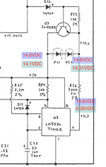
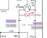
I just measured the voltage across this junction where the LED would be and after the timer opens the circuit (starts off at 0.7 mv) and then moves to 152 mV. This also only takes 30s, the famous repair guy 'fixed this' as it was taking too long, so ideally I would like the LED light to come on after 2m or so.
The timer circuit time I guess is a function of C22 and R65 maybe?
Thanks, very educational!!
The timer circuit time I guess is a function of C22 and R65 maybe?
Thanks, very educational!!
Those voltages don't sound right. When the circuit operates you should see around 14 volts across the now removed opto's.
If Q3 is on then that would account for the low voltages and in that case you would have 14 volts on one end of the 300 ohm.
When pin 7 goes high you have 14 volts on both sides of the 300 ohm.
R65 and C22 do set the delay but because of the very high value of R65 this means that C22 must be a low leakage type like a tant, otherwise the leakage of the cap will stop it ever charging up.
The 2.2meg and 33uF would give a delay of about 80 seconds I would think and at that point pin 7 goes low.
Note that some current will flow through Q3 as well. So not all 40-some mA flow through the LED.
If you're trying to see if the optocoupler gets turned on, it may be easier to measure the voltage across the output of it.
Tom
If you're trying to see if the optocoupler gets turned on, it may be easier to measure the voltage across the output of it.
Tom
What value has he put in? and also is R65 still a 2.2 meg?
With just 14 volts available the 'short circuit current' via 2.2meg is just 14/2200000 which is just 6 micro amps. That is all that is available to charge the cap but as the cap voltage rises the voltage across the 2.2 meg falls and so even less current flows.
It is an exponential curve. So if the leakage of the cap is a few microamps (which is typical for a normal electrolytic) then the cap can not reach the full voltage as it charges.
Pin 7 voltage looks good. You might need a load of some sort in place of the opto's in order to see if the bit around Q3 is OK. If you have any kind of LED then just fit it and see. 40 milliamps won't kill it (the LED) but it might be very bright if it is a modern type.
so I had an old LED in the amp, that was previously part of an unused external power output, no longer used. The LED was parallel wired into the LED used for the power on. so they both lit up.
I connected this across the optocoupler and got nothing on it? Could this be the wrong type of LED?
bit confused :-(
I connected this across the optocoupler and got nothing on it? Could this be the wrong type of LED?
bit confused :-(
yeah - that's it, and I have removed the optocouplers.
it did not light with the existing LED, but the voltage across this was only 152 mV so I am guessing that's not enough?
it did not light with the existing LED, but the voltage across this was only 152 mV so I am guessing that's not enough?
It should light when pin 7 is close to zero. That is the vital voltage coming off the chip.
If it doesn't light then Q3 is probably on (and so shorting the LED out) If you have that '+15 mute' voltage going to diode D16 then that will be turning Q3 on and stopping it lighting.
If it doesn't light then Q3 is probably on (and so shorting the LED out) If you have that '+15 mute' voltage going to diode D16 then that will be turning Q3 on and stopping it lighting.
- Home
- Design & Build
- Parts
- Diodes, LEDs and Optocouplers