Wow, that PCB is huge! Any reason why you are using "chopped-up" groundplanes or is it just for cosmetics?
Let's hope the magic smoke doesn't appear 😉. Good luck on the debugging!
Let's hope the magic smoke doesn't appear 😉. Good luck on the debugging!
Not really that large as it may seem, remember the small IC's are SOICs not regular DIPs.
This is only a basic prototype for debugging, I do expect to have terrible noise performance because of construction. If everything goes well and I find a viable market, then I should redesign it double face, much more compact and with all IC's mounted directly on it instead of using carrier modules.
The ground planes are not really that, simply fillers to save in resist developer and copper etchant.
Rodolfo
I noticed, still, there's a lot of IC's on that board 🙂.ingrast said:Not really that large as it may seem, remember the small IC's are SOICs not regular DIPs.
Why did you make carrier modules in the first place? Was it to avoid having to make the whole PCB all over again in case you misrouted a trace?...then I should redesign it double face, much more compact and with all IC's mounted directly on it instead of using carrier modules.
I was thinking it was something like that. You'd save even more etchant if you left the fillers solid copper 😉.The ground planes are not really that, simply fillers to save in resist developer and copper etchant.
I'm awaiting the results with great interest.
Devil_H@ck said:
Why did you make carrier modules in the first place? Was it to avoid having to make the whole PCB all over again in case you misrouted a trace?
True, more precisely I was wary of my home PCB process with regards to the very fine lines required for the FIFO, ADC and DAC.
Being on carriers it was safer to discard small bad pcb's (sure it happened) than the whole board. And believe me a bad one at this detail level is unworkable.
A possible production board will be ordered to professional manufacturers who can do fine lines reliably and multilayer if required.
With regards to complexity, though it is no simple system, anyone can build it for a few bucks. IC's are free if requested from TI as samples (I got all of them that way and delivered UPS to my door in 48 hs. average) and the board should not be too costly either.
If I end up manufacturing the device, I will make boards available to members for the nominal cost.
Let's see how it comes out
Rodolfo
Luciano,
Everyone else here is trying to talk you out of using a DSP for this. Obviously no one bothered to look up the TAS3103 that you suggested. In fact, this little DSP chip is incredibly versatile and will provide delay and/or reverb with very little effort.
The TAS3103 is not a conventional DSP. You do not need to write audio processing algorithms for it, all that you need to do is configure it. It has various processing blocks which perform specific functions, such as filters (for EQ, lowpass, highpass, etc.), delay, reverb, mixing, etc. To use it, you need to connect it to a microcontroller using I2C and program the microcontroller to configure the various blocks to do what you want.
macboy said:Luciano,
Everyone else here is trying to talk you out of using a DSP for this.
Not fair macboy, please check again past posts...🙄
.. To use it, you need to connect it to a microcontroller using I2C and program the microcontroller to configure the various blocks to do what you want.
And this is no casual walk in the park either. Programming a uC for configuring the Audio Processor is relatively strightforward. More involved is the task to provide the user interface. Either you provide analoge voltage to pulse width or frequency converters or stepping switches with associated display feedback to tell the user what he has entered.
The approach I am following is purely hardware based, not the best or more flexible but cheap, fast and usable I guess.
And I will also pursue the DSP approach anyway, just for other level of systems.
Rodolfo
I just checked the datasheet of that chip and there's only place for +- 1300 samples for a reverb delay line. Isn't that too few to get a decend effect? I've got an Yngwie Malmsteen video and I guess he uses a delay of maybe half a second.
Just guessing here, I could be all wrong.
Just guessing here, I could be all wrong.
They specify 42 mS max at 48 KHz.
Must assume they knew what they were doing? I guess yes, though others request over 100 mS for predelay.....
Rodolfo
Must assume they knew what they were doing? I guess yes, though others request over 100 mS for predelay.....
Rodolfo
And even 100ms isn't much right? I mean, if you know Yngwie's songs you know what I'm talking about, I don't know what effects he uses, but it sounds like a quarted is playing in canon, I can't imagine a 100ms would be able to archieve that.
davesaudio said:did this project die a quiet death?

It is sleeping for a while for I am working on an important amplifier topology developement which may eventually lead to publication on one hand, and comercial products on the other.
It was shortly after my last post here I came across the idea, made the initial analysis and filed for a patent.
I hope to be able to resume this as soon as practical, apologies to those who had expectations on a quick result.
Rodolfo
polywotsit revived?
EPE have published "cybervox" project in july 2005.
Reverb via PIC and external DAC (sound familiar?), though they have upgraded to an 18F252.
🙂
amazing how simple the 18F pic code has become...
EPE magazine had a project called the "polywotsit", which used a PIC with ADC built in and an external DAC. Several effects are switch-selectable, all implemented in firmware. It uses 8bit converters, not state-of-the-art but probably equivalent to a bucket brigade chip. You might get some ideas from it, link is here
EPE have published "cybervox" project in july 2005.
Reverb via PIC and external DAC (sound familiar?), though they have upgraded to an 18F252.
🙂
amazing how simple the 18F pic code has become...
ingrast said:
It is sleeping for a while for I am working on an important amplifier topology developement which may eventually lead to publication on one hand, and comercial products on the other.
It was shortly after my last post here I came across the idea, made the initial analysis and filed for a patent.
I hope to be able to resume this as soon as practical, apologies to those who had expectations on a quick result.
Rodolfo
Ingrast ! Did it work ?

I'm very curious !
You have already done all this, so let's get a conclusion 😉
Thanks !
Thanks for your interest _nando_.
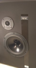
Yes, the project is going on. Attached are some shots, and I will be posting more soon.
At the moment I have 2 boxes working and have accumulated about 50 hs. of listening time with different material from classics to rock, and am quite satisfied. I will be presenting them for evaluation to knowledgeable people to get impressions and critique.
In the next post are the measurement results.
Rodolfo
Attachments
These are measurements performed on the prototype amplifier.
Due to differences among the audio nboard right and left channels, it seems amplifier output has actually less distortion than the input signal !. Of course this is not so, but underscores the fact the amplifier contribution is about an order of magnitude lower than the measurement baseline.
Rodolfo
Attachments

Are these TDA1097 chips available from you? I cannot find them in the local stores or ebay
In reply to:
I think you have to buy a reprint.. but no matter, I have the article and can scan it. The software (maybe should be firmware) can be downloaded free from the site, as you have seen. The PCBs (1 analogue & 1 digital) are available for only £7.61 for the pair according to the magazine with the article.
If anyone is interested, send me an e-mail from the link on my user info. There is no way to include attachments there, but it will generate a normal e-mail that will accept attachments in a reply. It's fairly large, 8 sides of A4, and includes PCB patterns. I'll see if I can send it uncompressed.
I have two TDA1097, made by Mullard, 1536 stage BBD chips that I never got round to using. They are pre-production prototypes. I have the datasheet too, and I have two TDA1022. I experimented with the latter but found them noisy, almost certainly due to the spaghetti layout I used. My layouts are better now. If you want to experiment with them, send your address in the e-mail. I have no time for it now.
- Status
- Not open for further replies.
- Home
- Source & Line
- Digital Line Level
- digital reverb or delay