If you say 'anything over 2.2V (or 0.8us pulse width) is 1' then you are doing digital.
Binary?
Jan
Yes. Unless you added, "and anything over 3.2V (or 1.2us) is 2" in which case you could be doing base-3 digital - useful for representing numbers like 1 1/3.
Sometimes a discussion here is like fishing. We all know the fish is on the line and being reeled in. The fish doesn't see it like that. The fish will wriggle and squirm and attempt to get free, while telling his friends that he is not really caught anyway; some fish may even believe that they are reeling in the fisherman!
Sometimes a discussion here is like fishing. We all know the fish is on the line and being reeled in. The fish doesn't see it like that. The fish will wriggle and squirm and attempt to get free, while telling his friends that he is not really caught anyway; some fish may even believe that they are reeling in the fisherman!
1 1/3 can never be represented by PWM; it can be approximated after the amplified, digital PWM is passed through a filter.
The comparison with fishing and all that nonsense is making me laugh...
The comparison with fishing and all that nonsense is making me laugh...
Isn't binary a digital system, with base 2?
The sole reason for class D using digital pulses to approximate the true analogue value, was to dramatically reduce power dissipation, power supply capability, physical size and save on heat sinking.
The sole reason for class D using digital pulses to approximate the true analogue value, was to dramatically reduce power dissipation, power supply capability, physical size and save on heat sinking.
Maybe you 2 fellas should get together and figure out a better way to convince us that binary is analog?
digital PWM is passed through a filter.
A digital one? When a plain old LC filter became a DSP?
all that nonsense is making me laugh...
😉
15 years ago I worked for a company who successfully designed a first sine wave lighting dimmer; a revelation for recording studios and theatrical companies alike -> no filament noise. I worked in a team that design that dimmer - and achieved the reconstruction of 50Hz sinewave signal 30,000 times in 20ms. First lot of 20 was installed at SOH
I don't understand where all the confusion is coming from here.
If you look at the input of a class D amplifier the analogue signal is combined with a high frequency switched signal such that the switched signal is modulated by the analogue. There is nothing discontinuous about this and there is no sampling at discrete intervals. The pulse width on the output is continuously variable and changes with respect to the analogue input signal.
Nothing about this system is digital, there is no conversion of an analogue signal into numbers anywhere, the analogue signal is present at all times from the input of the amplifier to the output, albeit modulated.
But lets say you connected the output of a class D amplifier to a digital input line of a computer, maybe via a PIC micro or something, then what? What are you going to do with that? It isn't in any form that any digital device would recognise. There is nothing regular about the output of a class D amplifier that you could try and exploit as a time base, as the timing changes in the rise and falling edges of the PWM signal are the analogue signal. This isn't like Manchester encoding or a SPDIF line where a recoverable clock + data has been encoded together. There is nothing to encode as the input is analogue.
If you wanted you could put a very fast ADC on the output of the class D amplifier and get it to convert the output into a digital signal. You could then perform digital signal processing, in audacity or similar, to remove the high frequency carrier and reconstruct your original analogue signal...but what'd be the point in that? The switching portion on the output of the class D amplifier is both unwanted but absolutely necessary to its operation. You'd have to capture the high frequency carrier in great detail, which would require a ridiculously fast ADC that would also throw away the high performance of the class D amplifier. That is if you wanted to capture the switching aspect of the class D amplifier. Which while commendable in principle, in reality, is completely pointless. You would be much better off low passing the output of the class D amplifier, removing the carrier and using a nice high quality audio ADC.
PWM comparator uses a threshold to encode incoming analog signal into PWM digital signal of 1 or 0. According to your understanding, the class D is digital.
So, by your reasoning, FM is a digital transmission also!
Just because the amplitude is fixed at 2 levels doesn't make it digital. To be digital, the time quantities need to be quantised also. If they are continuously variable, then it is analogue.
Ian

OT posts deleted. Don't make it official by trading insults folks. Argue and demonstrate your point on a technical basis.
Of course it can. You just need to use a base-3 number system. Digital is not restricted to being binary, although almost all digital systems are binary.Extreme_Boky said:1 1/3 can never be represented by PWM; it can be approximated after the amplified, digital PWM is passed through a filter.
Pulse widths from 0 to 0.4us are 0, 0.4 to 0.8us are 1, 0.8 to 1.2us are 2. Then 1 1/3 is 1.1, which is two pulses each about 1us wide. Simples!
How to add to the discussion, I ask:
There are circuits in which a HCF/CD 4069 is used linearly, biasing one or more of the inverters placing simply a high value resistor (Say 10Mohms) between input and output of it and coupling them capacitively. Then, the inverter is biased in class A although it is a "digital" circuit. This, indepently of distortion levels and true linearity, and supposing that the output level is not saturated to any of the supply rails.
The same may bu done with a NAND, NOR or anyone "digital" IC inverter from input to output (say, total inverting 180deg.), excepting those with Schmitt Triggers.
So, may I affirm that this is a digital amplifier? 😕
How to add to the discussion, I ask:
There are circuits in which a HCF/CD 4069 is used linearly, biasing one or more of the inverters placing simply a high value resistor (Say 10Mohms) between input and output of it and coupling them capacitively. Then, the inverter is biased in class A although it is a "digital" circuit.
The confusion arises because the 4069 IS NOT a digital circuit! How did you get that idea? It is a bunch of FETs in open loop. When you give it an input it amplifies it with very high gain and thus the output slams either into the supply or ground.
What you do with your 10 Meg is add feedback to an open loop amplifier so lower it's gain to a value that is usable in a linear (sort of) range.
Everything analog all the way.
Jan
And what about the crystal oscillator inside a microprocessor? It also starts as a class A device, and no doubt that it is a digital circuit!
And what about the crystal oscillator inside a microprocessor? It also starts as a class A device, and no doubt that it is a digital circuit!
Why is it a digital circuit? It's a square wave generator build from an open loop amplifier with positive feedback - is a square wave generator a digital circuit?? Are we calling any thing that isn't a sine wave 'digital' ??
Digital means representing something with a number - what has that to do with a square wave generator?
Jan
No doubt that it is a pure analog circuit. To become digital you need something more than just an oscillator.And what about the crystal oscillator inside a microprocessor? It also starts as a class A device, and no doubt that it is a digital circuit!
This does not mean that anything which uses a pulse width or a voltage is necessarily digital.
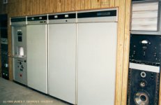
Never claimed that it is, quite the opposite. My first significant experience supporting an analogue PWM amplifier similar to the one below included a 20 kV, 100 kW power supply and operated at 800 kHz.
Otherwise we appear to be in substantial agreement.
Attachments
Way to answer the original question, guys.  🙄
🙄
I suppose the OP has now fled in horror, when all he wanted to know is what chipset will take a digital input.
I had several old Apogee amps that did. Certainly there are more modern chips for this. No one here knows any?
🙄I suppose the OP has now fled in horror, when all he wanted to know is what chipset will take a digital input.
I had several old Apogee amps that did. Certainly there are more modern chips for this. No one here knows any?
Ahh... the question wasn't even about the class D or amplification... So, the answer to the OP 🙂
AFAIR AKM has ASRC chips that can output 24bit/768kHz. How to connect some SPDIF in or other sources to the ASRC chip could be found on their datasheets and application notes.
The digital input first goes through some digital filtering on FPGA. The digital filter accept 24bit data at 768kHz.
Could anyone suggest how to obtain a digital audio input and feed to the fpga?
AFAIR AKM has ASRC chips that can output 24bit/768kHz. How to connect some SPDIF in or other sources to the ASRC chip could be found on their datasheets and application notes.
Way to answer the original question, guys.
I suppose the OP has now fled in horror, when all he wanted to know is what chipset will take a digital input.
Yeah we got distracted a bit 😁😂
- Status
- Not open for further replies.
- Home
- Source & Line
- Digital Source
- Digital audio input for a a digital class D amplifier