PHP:
They make the same basic error of thinking that something that switches is digital.
It's binary.
Ohh well.
Jan
Its Digital because its divided into fixed parts. 1.33 being Digital when meaning 1 1/3.
No. It does represent an analog value thus cannot be digital. Digital is about numbers.
In fact when a processor sends out a PWM signal it is converting the internal number representation into an analog value (most often a voltage derived from the supply voltage) - it's doing the DAC thing.
Jan
Digital is a representation of analogue.
1.33 could in reality be anywhere between 1.325 and 1.334 which is not the same as 1 1/3.
1.33 could in reality be anywhere between 1.325 and 1.334 which is not the same as 1 1/3.
1.33 could in reality be anywhere between 1.325 and 1.334
That would depend on the sample rate, no? And the bit depth.
Jan
Where is the sample rate or bit depth if it is analog?
Well I don't know, you were talking about a digital number 1.33 or thereabouts.
But I don't think this is going anywhere, so you can have the last word.
Jan
You are claiming PWM can only be analog when others claim it can also be digital.
If it is analog then it will have no problem with the value of 1 1/3.
If it is analog then it will have no problem with the value of 1 1/3.
NO! When will you get it? After the comparator the signal is purely switch-based. In a Class D amplifier it is never digital, because it is never a number.
It is a 100% digital signal, i.e. a number - either 1 or 0. It can just stay 1 longer than a digital signal you have stuck in your mind.
It is a 100% digital signal, i.e. a number - either 1 or 0. It can just stay 1 longer than a digital signal you have stuck in your mind.
No, it is not 1 or 0. It is some physical voltage. Power supply output impedance. Switch on-resistance. Switching speed. Their non-linearities. All of that is not numbers. All of that is analog. All of that is not constant. All of that is significant but nothing of that is ideal. Under high currents it is extra significant (it is why a "power" DAC is always a poor DAC, much worse than the low-current one). All of that seen by the receiver (the speaker, amplifier stages, driver, power stage, etc)... None of them "reading" strings of numbers. It doesn't matter for them if the voltage is + ~60V or - ~60V. It matters for them if it is 59.8V or 60.7V while for digital signal it wouldn't really matter. Whenever is it digital or analog decided clearly by how the receiver interprets them. If it recovers the original symbol sequence then it is digital. If it relies on some integrated value of an output voltage or current - it is pure analog. PWM in class D is always an analog signal because the receiver interprets it as such. This is not something to argue about except of purely religious reasons.
It is a 100% digital signal, i.e. a number - either 1 or 0. It can just stay 1 longer than a digital signal you have stuck in your mind.
The use of width rather than amplitude as the analog can be confusing to people who don't understand the operation of the circuit very well.
You are claiming PWM can only be analog when others claim it can also be digital.
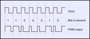
That's what I don't get either. Revisiting this graphic it appears to be a perfectly valid time multiplexed representation of 1100010 = 98.
Attachments
You also prefer to fight straw man? Where your opponent saw that PWM can't be digital signal in general?That's what I don't get either.
How this 98 is related to the PWM output of a switching power amplifier or a topic of the discussion?Revisiting this graphic it appears to be a perfectly valid time multiplexed representation of 1100010 = 98.
You also prefer to fight straw man? Where your opponent saw that PWM can't be digital signal in general?
How this 98 is related to the PWM output of a switching power amplifier or a topic of the discussion?
Reading the thread may be helpful.
Reading the thread may be helpful.
It was mentioned already several pages back, once, then answered, produced no disagreement from the poster, but a few pages of continuous complaints about the same. Reading the thread may be helpful. 😉
Also, how this can answer the second question?
Last edited:
1.33, 1.325, 1.334 and 1 1/3 are all numbers. They can all be represented exactly in an appropriate electronic circuit.Mark Whitney said:1.33 could in reality be anywhere between 1.325 and 1.334 which is not the same as 1 1/3
No. It is either 'up' or 'down', '+' or '-'. It is not 0 or 1.Extreme_Boky said:It is a 100% digital signal, i.e. a number - either 1 or 0.
Using pulse width (an analogue quantity) to indicate a binary value is not fundamentally different from using voltage (an analogue quantity) to do the same. In either case if the width/voltage is greater than some threshold then 1 is read; if less than some other threshold then 0 is read. Using an analogue quantity to indicate a binary value is how digital works. This does not mean that anything which uses a pulse width or a voltage is necessarily digital. On the contrary, it is only when there are thresholds etc. that it is digital; everywhere else (including Class D) it is analogue.rdf said:That's what I don't get either. Revisiting this graphic it appears to be a perfectly valid time multiplexed representation of 1100010 = 98.
No, it is not 1 or 0. It is some physical voltage. Power supply output impedance. Switch on-resistance. Switching speed. Their non-linearities. All of that is not numbers. All of that is analog. All of that is not constant. All of that is significant but nothing of that is ideal. Under high currents it is extra significant (it is why a "power" DAC is always a poor DAC, much worse than the low-current one). All of that seen by the receiver (the speaker, amplifier stages, driver, power stage, etc)... None of them "reading" strings of numbers. It doesn't matter for them if the voltage is + ~60V or - ~60V. It matters for them if it is 59.8V or 60.7V while for digital signal it wouldn't really matter. Whenever is it digital or analog decided clearly by how the receiver interprets them. If it recovers the original symbol sequence then it is digital. If it relies on some integrated value of an output voltage or current - it is pure analog. PWM in class D is always an analog signal because the receiver interprets it as such. This is not something to argue about except of purely religious reasons.
Very good, thanks for that explanation.
Jan
...it is only when there are thresholds etc. that it is digital; everywhere else (including Class D) it is analogue.
PWM comparator uses a threshold to encode incoming analog signal into PWM digital signal of 1 or 0. According to your understanding, the class D is digital.
I was talking about using a threshold to read the signal, not a threshold to generate the signal.Extreme_Boky said:PWM comparator uses a threshold to encode incoming analog signal into PWM digital signal of 1 or 0. According to your understanding, the class D is digital.
If you say 'anything over 2.2V (or 0.8us pulse width) is 1' then you are doing digital.
If you say 'X volts at the input is represented by a pulse width of 0.5X us' then you are doing analogue.
- Status
- Not open for further replies.
- Home
- Source & Line
- Digital Source
- Digital audio input for a a digital class D amplifier