From post #115: DiAna, a software Distortion Analyzer
Are you using integer arithmetic or double-floats? I can understand the problem with too many samples in a small number of bins with integer arithmetic, but not with double-floats.
Hi David,
No, the warning is correct.
Nope.
Nope.
Let me explain how averaging works and why "sample rate is whole multiple of frequency"should be avoided.
Input samples are mapped into a fixed interval, ranging from 0 to 2pi (by means of modulo 2pi arithmetic).
In order to make this stream of data manageable, this interval is subdivided in 1024 bins (actually an array 1024 x 80 bits) and each sample, after the fundamental has been subtracted (leaving only the residual), is accumulated in one of these bins. ...
Cheers, E.
Are you using integer arithmetic or double-floats? I can understand the problem with too many samples in a small number of bins with integer arithmetic, but not with double-floats.
The problem is that if the whole cycle fits in exactly say 1024 samples, then you will only get samples at the same places in the cycle. But if it needs say 1024.111111111... samples, you get samples in different places on each cycle. This way you get more data and when you collapse all the cycles it's like having one cycle with as many unique samples as you took the measurement with.
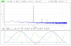
I still do not understand the issue. I am developing a Spectrum Analyzer using Octave (MatLab) and find that if the fundamental F1 is an exact divisor of the sampling frequency Fs, and if there are an integer number of cycles of F1 in the signal, then I do not need to apply a window function to the signal before the FFT, (ie. I use a rectangular window), and the resulting spectrum is excellent, as shown in this image:
Attachments
I forgot to mention that this code runs real time, updating at an arbitrary rate of buffers/sec = Hz/bin (your choice), up to 10 or so. It requires about 15% of each of 4 cores of an AMD FX-4100 Quad-Core Processor.
...I am developing a Spectrum Analyzer using Octave...
Interesting! How do you deal with the (realtime) audio in/out in Octave? What operating system are you using?
(sorry for getting off topic)
Interesting! How do you deal with the (realtime) audio in/out in Octave? What operating system are you using?
(sorry for getting off topic)
For real-time audio in Octave I use playrec: Playrec - What is Playrec? and PlayrecForMatlab * GitHub.
I have only tested my Octave Spectrum Analyzer code with Fedora 27 Linux, but another DIYAudio regular is trying to get playrec working with Windows in order to try out the Spectrum Analyzer.
[...]this interval is subdivided in 1024 bins (actually an array 1024 x 80 bits) [...]
Hi Lynn,From post #115: DiAna, a software Distortion Analyzer
Are you using integer arithmetic or double-floats? I can understand the problem with too many samples in a small number of bins with integer arithmetic, but not with double-floats.
Normally, DiAna uses long doubles (80 bits), but currently the demo version uses "only" 64 bits (i.e. doubles), because my compiler for long doubles generates code that triggers some (silly) AV scanners who think it contains a virus (false positives).
Cheers,
E.
The problem is that if the whole cycle fits in exactly say 1024 samples, then you will only get samples at the same places in the cycle. But if it needs say 1024.111111111... samples, you get samples in different places on each cycle. This way you get more data and when you collapse all the cycles it's like having one cycle with as many unique samples as you took the measurement with.
Exactly !
I still do not understand the issue. I am developing a Spectrum Analyzer using Octave (MatLab) and find that if the fundamental F1 is an exact divisor of the sampling frequency Fs, and if there are an integer number of cycles of F1 in the signal, then I do not need to apply a window function to the signal before the FFT, (ie. I use a rectangular window), and the resulting spectrum is excellent, as shown in this image:
Hi Lynn,
Firstly, DiAna works radically differently (it's a distortion analyzer and not just an ordinary spectrum analyzer). Instead of averaging a number of FFT's, it averages the signal first and then takes the FFT. IOW, just the other way around.
The bins I was talking about, are not FFT bins (in the frequency domain), rather bins in the time domain (modulo 2pi), spanning just one cycle of the fundamental. For this reason one doesn't need a window at all, but as keantoken also explained, one should take care that all bins contain some data, otherwise some high order harmonics might be attenuated.
Cheers,
E.
About the next version
Hi Kean and Demian,
I'm still busy with the filter stuff. As for notch filters, the program is ready. One can characterize a notch filter (i.e. measure amplitude and and phase) and save the result, as well as use these data to compensate for amplitude and phase shifts in order to reconstruct the original residual. This works fine.
As for high pass filters, I first looked at FIR filters, because of the linear phase response. But these kind of filters are too computational-intensive. So I'm now implementing a IIR filter. However, in this case one have to compensate for amplitude and phase. Since I've already done this for notch filters, it's quite easy to use the same method for LP filters.
I'll let you know (of course) when the program is ready.
In the meantime, and this is really embarrassing, the calibration procedure of version 1.53.7 contains a bug. The calculated calibration factors are 1.414 too high. As it applied to the ADC and DAC as well, at first glance it looked okay (the one error compensates for the other error) and doesn't attract my attention, but when measuring the real voltages, it appeared to be wrong. This bug is corrected in the next version. BTW, why has nobody told me about this error?
Cheers,
E.
I used a brickwall HP filter to get rid of hum in low-amplitude tests so they could be processed. The problem is the harmonics get shifted in phase if the corner frequency is anywhere near the fundamental. Do you think you could implement a HP filter that does not alter the phase?
Going back to my proposal let me outline what I see.
If you have a high pass filter in the chain the sweep will automatically collect phase/amplitude changes that come from that.
[..]
This is not a simple/quick thing to create so I hope it's not too much to ask.
[..]
I would collect the loss(gain)/phase info of the filter as part of the cal process every time its set up since you may have a number of filters or something like a B&K 1607 tuneable notch.
Hi Kean and Demian,
I'm still busy with the filter stuff. As for notch filters, the program is ready. One can characterize a notch filter (i.e. measure amplitude and and phase) and save the result, as well as use these data to compensate for amplitude and phase shifts in order to reconstruct the original residual. This works fine.
As for high pass filters, I first looked at FIR filters, because of the linear phase response. But these kind of filters are too computational-intensive. So I'm now implementing a IIR filter. However, in this case one have to compensate for amplitude and phase. Since I've already done this for notch filters, it's quite easy to use the same method for LP filters.
I'll let you know (of course) when the program is ready.
In the meantime, and this is really embarrassing, the calibration procedure of version 1.53.7 contains a bug. The calculated calibration factors are 1.414 too high. As it applied to the ADC and DAC as well, at first glance it looked okay (the one error compensates for the other error) and doesn't attract my attention, but when measuring the real voltages, it appeared to be wrong. This bug is corrected in the next version. BTW, why has nobody told me about this error?
Cheers,
E.
Hi Lynn,
Firstly, DiAna works radically differently (it's a distortion analyzer and not just an ordinary spectrum analyzer). Instead of averaging a number of FFT's, it averages the signal first and then takes the FFT. IOW, just the other way around.
The bins I was talking about, are not FFT bins (in the frequency domain), rather bins in the time domain (modulo 2pi), spanning just one cycle of the fundamental. For this reason one doesn't need a window at all, but as keantoken also explained, one should take care that all bins contain some data, otherwise some high order harmonics might be attenuated.
Cheers,
E.
Thank you for the concise explanation. I now better understand how your method differs from FFT based spectrum analyzers. However, I am not sure how the analytic results might be better than that produced from "ordinary" spectrum analyzers, which can produce amplitude and phase information about individual harmonics.
Sure, also an ordinary spectrum analyzer will show the individual harmonics, but it also shows spurious components, not related to the fundamental, which in turn complicates the assessment of the real harmonic distortion. Also noise is easily and effectively suppressed, which otherwise "pollutes" the spectrum.Thank you for the concise explanation. I now better understand how your method differs from FFT based spectrum analyzers. However, I am not sure how the analytic results might be better than that produced from "ordinary" spectrum analyzers, which can produce amplitude and phase information about individual harmonics.
A nice example is a design flaw of some Lynx sound cards, which was not discovered using an Audio Precision analyzer, but clearly visible with DiAna.
Doing it "the other way around" has also a historical reason: The development of DiAna dates back to the time that audio ADC's as we know them today, were not available yet. Instead, there were SAR ADC's with relative low sampling rates. Normally, it would not be possible to capture signals and it's harmonics above the Nyquist frequency, but DiAna reconstructs the original signal, so to speak. This way it can show spectral components far beyond the sampling frequency (provided that they are not filtered away by means of an anti-alias filter). Think of one of the first "sampling scopes", showing signals up to 300MHz, while sampling at only 50Hz.
By the way, DiAna also calculates a regular/traditional FFT, though primary intended to show spurious stuff.
Cheers,
E.
Last edited:
I will upload the fix when the high pass filter is also ready.Should have just fixed it and told everyone to upgrade.
Till then one should enter the calibration factors "manually".
Cheers,
E.
Firstly, DiAna works radically differently (it's a distortion analyzer and not just an ordinary spectrum analyzer). Instead of averaging a number of FFT's, it averages the signal first and then takes the FFT. IOW, just the other way around.
That may be a silly question, and I am very late to the party, but I don't get it. The data is essentially the same in the time domain and in the frequency domain. Both worlds are equivalent to each other via the Fourier transform, which is "lossless". So how is it "better" to do the averaging in the time domain rather than in the frequency domain? Wouldn't that give the same result in the end, since it's the same data?
I think that if he use a time domain synchronous averaging to only retrieve
THD products of input signal (coherent harmonics) , then , this process will remove non-coherent noise or spurious. Resulting FFT's will not been the same.
Frex
THD products of input signal (coherent harmonics) , then , this process will remove non-coherent noise or spurious. Resulting FFT's will not been the same.
Frex
One must consider the Nyquist–Shannon sampling theorem. The Nyquist frequency (Fs/2) limits the frequencies that can be represented in a signal sampled at Fs samples/sec. An audio sound card is not capable of sampling in the manner of sampling oscilloscopes.
One must consider the Nyquist–Shannon sampling theorem. The Nyquist frequency (Fs/2) limits the frequencies that can be represented in a signal sampled at Fs samples/sec. An audio sound card is not capable of sampling in the manner of sampling oscilloscopes.
That's right. A delta sigma ADC can't do that. But a SAR ADC with a suitable front-end and sample/hold circuit is capable to capture higher frequencies, That's how "under sampling" works. I hope that Frex's ADC is capable to break the Fs/2 barrier.
The LTC2380-24 itself have 34MHz linear bandwidth.
The analog input stage use fast buffer and two cutoff frequencies can be selected.
Anyway, there is also a 1.5 MHz passive low-pass filter at the ADC inputs to improve SNR.
Of course i can be modified if larger analog bandwidth is required.
lhquam, for more details about under-sampling, look here : Undersampling - Wikipedia
Frex
Why should the conversion technology matter with regard to the logical Nyquist theorem? If a SAR ADC outputs sample values at equal times, how is it different from a delta sigma or parallel ADCs outputting sample values at the same frequency?
IMO every ADC has a S/H element.
IMO every ADC has a S/H element.
- Home
- Design & Build
- Equipment & Tools
- DiAna, a software Distortion Analyzer