I had before. They actually measure 0.000uF but my Fluke 16 meter cant really measure pF very well. Ohm tests look normal. I think thats correct because 100J is supposedly 10pF (0.00001uF). J is 5% tolerance.
It's hard to believe that that's a cap with such low value for the size.
Do you have an assortment of capacitors down to about 10pF?
Do you have a signal generator that will go to about 20kHz?
Do you have an assortment of capacitors down to about 10pF?
Do you have a signal generator that will go to about 20kHz?
I have a lot of caps but I think the lowest I see here is about 47pF. Checking parts boards now for maybe something lower..... but they're tiny compared to this amp's.
Yes my generator will go from ~0 through 3.5MHz
Yes my generator will go from ~0 through 3.5MHz
Capacitors will act the same as series resistors. If two of the same value are connected in series and a signal applied across them, they will divide the signal in half at their common terminals. The frequency required will depend on the value so you'll have to use lower frequencies for larger caps.
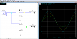
If you connect the brown cap in series with the 47pf cap, most of the voltage will be across the lower value capacitor (the brown cap if it's actually a 10pf). The attached is an example. Ignore the resistor. It's there to make the simulation run properly.
If you connect the brown cap in series with the 47pf cap, most of the voltage will be across the lower value capacitor (the brown cap if it's actually a 10pf). The attached is an example. Ignore the resistor. It's there to make the simulation run properly.
Attachments
Thanks for the tip.
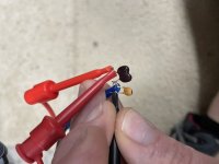
I put the weird cap in series with a known 47pF cap, and pushed a 20KHz, 1v sine way across the pair (Red-Black leads). The 47pF cap measued 0.35vAC across it, and the bigger one measured 0.65vAC. So that means the bigger one is smaller than 47pF.
Im thinking its probably a ~500v cap.
I put the weird cap in series with a known 47pF cap, and pushed a 20KHz, 1v sine way across the pair (Red-Black leads). The 47pF cap measued 0.35vAC across it, and the bigger one measured 0.65vAC. So that means the bigger one is smaller than 47pF.
Im thinking its probably a ~500v cap.
Attachments
You could be right but it's an odd choice. I thought that it looked like it could be two tantalum caps in series (likely reverse series) to make a bipolar cap. That seems to be proved wrong.