Oh man I thank you for taking the time on this one. I didn't realize you took a good chunk of weekend for me. I appreciate it and thank you.
To be honest, the amp did fail with 2sc1845, MPSA42, & MJE182 in Q62, but the 2n6488 is seemingly holding temperature down a lot better but still running extremely hot. I ran the amp with a music source for about 15 minutes bouncing it off clipping no load and that transistor is hot, but holding better. I then ran it really hard for about 15 seconds and it ran up to 220F without a sync on music input. It raises in temperature 20x faster with my frequency generator signal however.
The one thing that I did notice was, the owner did have the +14DB gain button pressed. Its an input range button and made the amp likely clip very hard in no time at all.
If it helps any, this Q62 seems to really only be providing -35vDC to many other components after it. Its acting like a relay for negative rail to several other components which are not getting hot or failing. One has to be an issue.
E: -35.8vDC
C: 0
B: -35.2
I wonder, would it be possible or unsafe if I just put say a 10ohm 1/4w resistor as a jumper across E-B pads?
E: -35.8vDC
C: 0
B: -35.2
I wonder, would it be possible or unsafe if I just put say a 10ohm 1/4w resistor as a jumper across E-B pads?
Do you mean E-C?
As a test, it may be useful but I don't see it as a solution for a paying customer.
As a test, it may be useful but I don't see it as a solution for a paying customer.
NO. B-E.
C is connected back to the muting circuit.
I agree testing only. I put a 10 ohm 1w resistor across B-E pads of Q63, and lo-and-behold the amp is holding unloaded output straight out to massive clipping. Jumping seems to have worked for testing. I am going to perform some high-output load tests to see if anything else pops out... That being said, CH2 now has a very slight turn-on/off pop. Hmmm
There are two good measuring muting transistors; Q52, Q53. Each channel has the same. They're all measuring the same voltages on pads whether or not the amp is clipping.
Would you happen to have some sort of schematic which might detail a bit of the muting circuit?
Last edited:
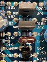
Hey um... Q63 backwards?
On the board/pads,
1: Base
2: Collector
3: Emitter.
Again, the -36v is crossing over B-E.
Photos next comparing CH1 and CH2 in this location.
On the board/pads,
1: Base
2: Collector
3: Emitter.
Again, the -36v is crossing over B-E.
Photos next comparing CH1 and CH2 in this location.

Also I must apologize. I hope this wasn't a time waister for you, but I realize I've been saying Q62 was over heating, when all along its been Q63. Originally a 2sc1845 that DID short across E-B originally. Still figuring this out. Sorry about the confusion.
Last edited:
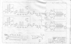
I've attached the PPI diagram that shows the muting transistors.
It's rare that current would intentionally be passed through the base and emitter.
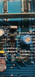
In your amp do you have leg 3 connecting to the brown capacitor in front of it?
Can you read the value of that capacitor?
It's rare that current would intentionally be passed through the base and emitter.
In your amp do you have leg 3 connecting to the brown capacitor in front of it?
Can you read the value of that capacitor?
Attachments
Yes to your question leg3 to the brown cap. That cap is marked CMD100J. I actually tried swapping CH1's cap with CH2's. That didn't help CH2. I also tried removing that cap completely from CH2, and when I do the amp will not power up; and R186 smokes and the amp draws excessively (About 5A)
Taking an inexperienced guess here, there may be something inherently wrong with the component in this/these locations on all channels. I again went back to test CH1/3/4 and the NPN part in those channels similarly will get rather hot. I'm seeing 170F on the NPN for the channel when I run that channel heavily into clipping, though without failure. All channels ARE running current across B-E.
What is the collector connected to?
Do you see the same voltage on all terminals of the corresponding transistors on the other channels?
Does the voltage on the collector change when you drive the channels to clipping?
Do you see the same voltage on all terminals of the corresponding transistors on the other channels?
Does the voltage on the collector change when you drive the channels to clipping?
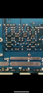
Q63 collector is connected to secondary/channel ground, which is also connected to the jFet muting circuits' drain. See photos and green line.
yes all 4 channels are connected like this, and all 4 have voltages like:
B: -35.4
C: 0
E: -35.6
voltage on collector stays at 0. It’s well connected to secondary ground.
yes all 4 channels are connected like this, and all 4 have voltages like:
B: -35.4
C: 0
E: -35.6
voltage on collector stays at 0. It’s well connected to secondary ground.
Attachments
The 10ohm resistor across B-E in post #26 photo is a possible solution. Actually I checked all channels and they ALL have a turn on/off pop anyways. Seems to me the muting circuit isn't working anywhere in this amp.
This amp has passed long term testing under high current low impedance heavily clipped output on CH1/2/3/4. CH2 actually has nothing abnormally heating up at all, whereas CH1/3/4 have that same NPN transistor running very hot but not over 200F, and not failing.
Suggestions? Conclusions?
This amp has passed long term testing under high current low impedance heavily clipped output on CH1/2/3/4. CH2 actually has nothing abnormally heating up at all, whereas CH1/3/4 have that same NPN transistor running very hot but not over 200F, and not failing.
Suggestions? Conclusions?
What's the DC voltage on the gate terminals of the jfets from the time remote is applied and for the next 10 seconds?
Both turn on and off pops happen at 0v immediately when applying rem, and about 5 seconds after removing rem.
Can you pull and compare the value of the capacitor connected to the hot transistors to the one in ch2?
- Home
- General Interest
- Car Audio
- Diamond Audio D9 800.4