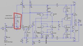
there are resistors on each end of the pot, but not to the wiper (pins 1 & 3). r18 and r19.
cheers
cheers
Last edited:
Ah, forgive me, its been a while since I looked at the schematic. I had it confused with another.
Ok so it appears the wiper is already directly connected the rail. This is fine.
I will look at it a bit deeper when I arrive home.
Ok so it appears the wiper is already directly connected the rail. This is fine.
I will look at it a bit deeper when I arrive home.
I doubt you can null such an amount of DC with the trimpot. I think the bias currents have to be balanced to get a fairly low DC-offset to start with and then fine trim it with the pot.
I think the bias currents have to be balanced to get a fairly low DC-offset to start with and then fine trim it with the pot.
Actually that's precisely what the pot does. 🙂 Just in a different way.
I think the reason he is running out of adjustment is that the values of R18 and R19 could be too low is his case.
I don't have any trouble adjusting mine to zero AC couple or DC coupled, but we could be using different values at some key components.
Cheers!
Russ
what are your r18 and r19 russ?
I still think i may hae a build error, but looking back through the thread, another guy had the same issue.
I still think i may hae a build error, but looking back through the thread, another guy had the same issue.
I use 470R But it should be ok to go up to 1K(the same value as the pot).
Hi Russ
I get the same problem on the off-set adjustment.
According to the BOM, R18/19-221R, Roff-set 10K and
I'm using 220R for R18/19, should they be changed to 470R
or higher? and What is the value of Roff-set? 1K??
Cheers
TS
Thats the values i used. I will have a mess with one fo the boards when i get time. First thing will be to try 1k for r18/19 which will give more adjustment.
Thats the values i used. I will have a mess with one fo the boards when i get time. First thing will be to try 1k for r18/19 which will give more adjustment.
Hi adamus
Will you also change the Roff-set to 1K?
I'm waiting for your test results 🙂🙂
Cheers
TS
not intitiallly. Will report back when i get it tested. I got knocked off my bike by a car and am still very dizzy, so probably not ideal condition for electronics.
I got knocked off my bike by a car and am still very dizzy, so probably not ideal condition for electronics.
Hi adamus
Sorry to learn that hope you'll recover soon.
Cheers
TS
just whipped out the 221r and replaced with 2k (r offset 10k) and I get closer to dialing out the offset, but with the wiper at max anticlockwise i still have about 200mv offset. This is without the inputs shorted as i will be ac coupling.
I have asked a couple of times, but has anyone got these working other than Russ. I am sure we can get them going, but i wonder how others have differed from me.
I have asked a couple of times, but has anyone got these working other than Russ. I am sure we can get them going, but i wonder how others have differed from me.
Last edited:
even though with shorted inputs i can easily remove offset?
. I matched the HFE of the transistors, all bwteen 250 and 300
Thinking about it. i am pretty boared so i could measure the transistors.
. I matched the HFE of the transistors, all bwteen 250 and 300
Thinking about it. i am pretty boared so i could measure the transistors.
Last edited:
I'm still voting for:
1. current source to the positive input
2. balancing the bias currents with "the right" resistor values + input cap
3. input cap + cap between R3 and ground
1. current source to the positive input
2. balancing the bias currents with "the right" resistor values + input cap
3. input cap + cap between R3 and ground
nelson, i have 2sk170's at hand. forgive my knowledge, but are we lookign at r25 to be replaced by a css.
I forgot a #4 on my list: the useage of JFET input transistors instead of bipolar, but this changes the sound quite dramatically.
Adamus, this is what I mean. The resistor R3 has to be trimmed to balance the bias currents. In LTSpice it's 6.55 uA. I can't remember what numbers it was in real life, but it was not too far from this. R25 should not be altered. Since you already have an SK170, you could at least try it on one channel. You have the right value when the DC offset doesn't vary with the turning of the volume pot.
Adamus, this is what I mean. The resistor R3 has to be trimmed to balance the bias currents. In LTSpice it's 6.55 uA. I can't remember what numbers it was in real life, but it was not too far from this. R25 should not be altered. Since you already have an SK170, you could at least try it on one channel. You have the right value when the DC offset doesn't vary with the turning of the volume pot.
Attachments
Last edited:
I'm still voting for:
1. current source to the positive input
2. balancing the bias currents with "the right" resistor values + input cap
3. input cap + cap between R3 and ground
I'm sorry I looked at the wrong schematic. It should be:
3. input cap + cap between RG and ground
Its been bugging me that i couldnt get this going.
if i have anything over 20mv over r1-r6 i cant dialout offset with input caps in place.
checking over the boards, the only discrepancy i see is r11 is 15k and not 16.2k (on diamante schemetic, not the schamatic nelsonvandal has shown)
offset is not stable, it will fluctuate +/- 6 mv and takes at least a minute to settle.
The key is to match the base currents at the input pair. Starting with as close to a matched pair as possible is a good start. Also consider the resistors in the feedback loop and at input. Try to keep the impedance from input to GND and output to GND roughly the same.
- Home
- Amplifiers
- Solid State
- Diamante -a discrete medium power opamp