yes.
shorted > 50k pot > amps
Which made me look at the input wiring... looks ok at first glance.
Can someone give me a sanity check. If input is shorted to ground, at any position of the pot, should the resistance (the amps) between input and ground be zero? Its not in my case. its goes as high as 10k.
shorted > 50k pot > amps
Which made me look at the input wiring... looks ok at first glance.
Can someone give me a sanity check. If input is shorted to ground, at any position of the pot, should the resistance (the amps) between input and ground be zero? Its not in my case. its goes as high as 10k.
Last edited:
This is a bipolar input amp. The input currents has to be balanced somehow. Either with an input cap and "the right" resistor (positive input to ground, negative input to ground and feedback) values or with an appropriate CCS to the positive input.
can you go slower for me nelson.
are you saying this cant be used for the application i intend? can you explain why this is any different to a 2 channel headphone amp buillf
are you saying this cant be used for the application i intend? can you explain why this is any different to a 2 channel headphone amp buillf
Read the part "Balancing the Input Bias Currents" @ Working with Cranky Op-Amps or google about input bias currents and bipolar input opamps. With JFET input opamps this problem doesn't exist.
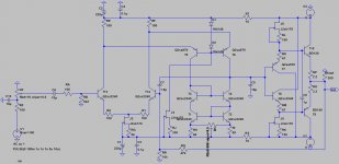
Even in a perfect simulator world the second of the circuits below will have a DC offset varying between 0 and 100 mV depending on the volume setting if the bias currents aren't balanced. In real life it's even worse.
The 1st schematic is how such a circuit could look like. Note that the pot is now 1k, so the input impedance will be quite low. You could tenfold the resistor values and use a 10k pot, but that solution has it's own problems with a much higher noise level and problems finding small enough comp caps.
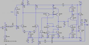
Another solution is the 2nd schematic with a CCS to balance the input bias current. Note that with this method there's no need for input caps. I just read in a thread here that a JFET at this low current wont act as a good current source. I can't hear the increase in noise they were talking about, and when simulated it's barely noticeable. I don't find it deteriorate the sound at all.
Even in a perfect simulator world the second of the circuits below will have a DC offset varying between 0 and 100 mV depending on the volume setting if the bias currents aren't balanced. In real life it's even worse.
The 1st schematic is how such a circuit could look like. Note that the pot is now 1k, so the input impedance will be quite low. You could tenfold the resistor values and use a 10k pot, but that solution has it's own problems with a much higher noise level and problems finding small enough comp caps.
Another solution is the 2nd schematic with a CCS to balance the input bias current. Note that with this method there's no need for input caps. I just read in a thread here that a JFET at this low current wont act as a good current source. I can't hear the increase in noise they were talking about, and when simulated it's barely noticeable. I don't find it deteriorate the sound at all.
Attachments
Last edited:
thanks nelson. both options arent particularly satisfactory to me, i dont particularly want a cap in there, and the Jfect Css will require me tearing down the whole think again.
why do you think this is occuring in my build, yet has only been mentioned by 1 other builder. any ideas?
why do you think this is occuring in my build, yet has only been mentioned by 1 other builder. any ideas?
What's the gain? Is it the original circuit with gain 2? In that case 800 mV DC offset seems very much. How well did you match the transistors?
BTW, a JFET CCS should be easy to retrofit, don't you think?
BTW, a JFET CCS should be easy to retrofit, don't you think?
x2. offset varies with the volume pot from zero (log - small increments until high vol then larger and larger increments),
transistors were matched the best i couyld, hfe of 270 for the 550 and hfe of 290 for the 560.
transistors were matched the best i couyld, hfe of 270 for the 550 and hfe of 290 for the 560.
Last edited:
What's the gain? Is it the original circuit with gain 2? In that case 800 mV DC offset seems very much. How well did you match the transistors?
BTW, a JFET CCS should be easy to retrofit, don't you think?
yes - but my casing is a little intricate for this one. I was hoping i had made a glaring error somewhere. still wonder if i ts my input wiring. I am using a stepped pot that has no wiring diagram, but the way i have wired it seems sensible on the mulitmeter.
Well, maybe you should double check all the wiring again. Does it sound ok? No hum or noise? No hole-in-the-middle-sound indicating a grounding issue?
I havent listened to it yet, i dont fancy that mush offset through the phones. I'll double check with a clear head tomorrow. I may even try it with a simple 1 channel pot that i know i cant get wrong!.
checked the wriing again (infact redid it). Same result. could someone check a working build. The reason i ask, typically people check the dc offset with the pot set to min. I only noticed the problem when i turned the pot up.
maybe i have something wrong on the boards.
maybe i have something wrong on the boards.
This is not uncommon with bipolar input opamps that are DC coupled at the inputs.
The cure is a to use input caps. 2uf should be plenty.
Cheers!
Russ
The cure is a to use input caps. 2uf should be plenty.
Cheers!
Russ
thank Russ.
Any other cures (even if it means surgery?)
I am not a big fan of caps in the signal path.
Any other cures (even if it means surgery?)
I am not a big fan of caps in the signal path.
Well you could use a servo. 🙂
Or you can use a volume control that has a constant output impedance. Like Joshua tree.
Cheers!
Russ
Or you can use a volume control that has a constant output impedance. Like Joshua tree.
Cheers!
Russ
The two input pins of an opamp need to have the same resistance to source the same current to develop the same voltage. It's the input offset current in the specification.
The diamante behaves similarly.
Even when the input transistors are perfectly matched. it's the input offset voltage that ultimately generates the output offset voltage.
If you make the resistance conditions on the +IN identical to the -IN and hold the matched transistors at the same temperature then the input offset voltage at both input pins will be identical and the output offset will be near enough zero.
Look at your circuit diagram and see if the +IN is actually identical to the -IN.
Last edited:
This is not uncommon with bipolar input opamps that are DC coupled at the inputs.
The cure is a to use input caps. 2uf should be plenty.
Cheers!
Russ
You still have to balance the input currents with one of the three methods mentioned: "balanced resistors", a current source to the input pin or a servo.
I still think a JFET as a current source is the simplest, cheapest and best solution. The surgery is minor and could easily be reversed.
Last edited:
There is a pot on the board to nullify the offset.
If you AC couple the input you need only adjust it to zero.
If you AC couple the input you need only adjust it to zero.
trouble is, when you ac couple, you cant null the offset. it sits at around 1v and there isnt adjustment in the pot.
I still wonder if i have a specific biuild issue. Could someone with a working headamp please emaure the offset at min and max volume.
Thanks
Adam.
I still wonder if i have a specific biuild issue. Could someone with a working headamp please emaure the offset at min and max volume.
Thanks
Adam.
Try reducing or shorting the resistor that is as the wiper of the offset nuling pot.
Cheers!
Russ
Cheers!
Russ
Sorry for the typos in the above post. That's what happen when I try to reply quickly from my Droid. 🙂
There is a resistor at the wiper of the DC null pot. If you short it or reduce it you should be able to fully nullify the offset. Let me know if that works.
Cheers!
Russ
There is a resistor at the wiper of the DC null pot. If you short it or reduce it you should be able to fully nullify the offset. Let me know if that works.
Cheers!
Russ
- Home
- Amplifiers
- Solid State
- Diamante -a discrete medium power opamp