after being out for a while (elbow surgery) I finally fired my borads up.
Do i need to have the pot connected to get the offset reading correct?
Bias dials in fine, but all of them exhibit dc offset of around 0.5v (with inputs open).
Do i need to have the pot connected to get the offset reading correct?
Bias dials in fine, but all of them exhibit dc offset of around 0.5v (with inputs open).
adamus said:after being out for a while (elbow surgery) I finally fired my borads up.
Do i need to have the pot connected to get the offset reading correct?
Bias dials in fine, but all of them exhibit dc offset of around 0.5v (with inputs open).
That second pot is what you use to adjust out the offset.
You should be able to dial it out with the offset pot either way. If you can't then I would double check things. First measure the current through both sides of the input pair. It should be close to equal.
all sorted, inputs shorted and offset is bang on zero.
Just the slight task of casing these up now!
Cheers chaps.
Just the slight task of casing these up now!
Cheers chaps.
be very careful how you use these boards.adamus said:all sorted, inputs shorted and offset is bang on zero.
The power amp must have some method of detecting and/or eliminating the input offset if you disconnect the inputs to the Diamante buffers/amplifiers.
Reducing the resistor at the input to GND should tame the offset with no source quite a lot. 10K should do fine.
I am using them as balanced headphone amp, so i certainly dont want to fry my headphones through stupidity (my own!)
I'll be using an amb audio E12, which i have spare from an old project, given these run off bipolar supplies, its dc offset sensing abilities will work.
I'll be using an amb audio E12, which i have spare from an old project, given these run off bipolar supplies, its dc offset sensing abilities will work.
I am building my first exactly as the original schematic.Russ White said:Reducing the resistor at the input to GND should tame the offset with no source quite a lot. 10K should do fine.
My second will have Lsk170 as the input pair.
The third will have a cascoded Lsk170BF245 input quad.
Yes, the cascode quad can fit the 6pads of the normal input pair.
All the pairs on the PCB will be thermally coupled, instant adhesive and three turns of 0.5mm copper wire.
AndrewT said:I am building my first exactly as the original schematic.
My second will have Lsk170 as the input pair.
The third will have a cascoded Lsk170BF245 input quad.
Yes, the cascode quad can fit the 6pads of the normal input pair.
All the pairs on the PCB will be thermally coupled, instant adhesive and three turns of 0.5mm copper wire.
Very cool. 😎
I look forward to seeing and hearing about that!!!
I actually have a layout for this amp that uses THAT semi devices for thermal coupling and matching.
AndrewT said:The third will have a cascoded Lsk170/BF245 input quad.
Clever man...I've read somewhere that is possible to emulate vacuum triode operation with proper Id and Vds over cascoded devices...Anyway "Borbely" type cascode always gives best THD in simulation and I've tried them all.
anyone do any tests with different bias? I have 25mv across r1 - 6 at the moment. Is it worth increasing to 10ma per device (50mv)
if you can find Borbely's ae699.pdf (jfets, the new frontiers, part2) fig 14b and fig17 show the cascoded LTP.
note the quad has 6 connections to the outside world just like a standard BJT LTP.
note the quad has 6 connections to the outside world just like a standard BJT LTP.
Hi,adamus said:anyone do any tests with different bias? I have 25mv across r1 - 6 at the moment. Is it worth increasing to 10ma per device (50mv)
if you adjust this ClassA output stage to the Vre=26mV (cold) then when it is asked to deliver more current it will move into ClassAB cleanly with minimum distortion. This is better than overbiasing the output stage.
The warmed up Vre including the effect of the internal Re will probably be in the range 15mVre to 20mVre.
Adjust your ClassA current by swapping out the standard 10r Re values and substituting lower values. If necessary add flagsinks to the To92 output devices and keep the voltages on the low side, or swap them to bd139/140 with 25C/W sinks.
I will try Re=5r for To92 devices giving Ib=~3.5mA * 3 and ClassA Ipk=~21mA.
I also plan to try 3r3 with To126 devices ClassA Ipk=~33mA
Re=1r0 would allow nearly 100mA of ClassA output.
Thanks for that andrew - much appreciated.
I am in the midst of mocking up the layout, and am stuggling for room in the case i have... unless i mount them to the vertical side of the case.
now i dont think i will have any thermal issues as this is not kicking out much heat at all with Vre at 25mv cold... but i am potentially opening the door for uneven heating and thus offset creep, or do you think its a none issue and i should get on with it!
if you bias the output stage to Vre~20 to 25mv then these will run cool using the 10r Re values. This will limit your classA output to <15mA
The hottest transistor, by far, isQ11
The hottest transistor, by far, isQ11
Next steps....
So about a year ago, I started thinking of variations on the Diamante theme.
One thing that struck me was that the diamond buffer was taking up a lot of board space. I looked at the datasheet of the LME49600 and realized it was exactly the same kind of cct I would implement discretely, but much more compact, and it offered built in features I would have to add, such as over current protection etc.
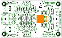
So I designed a new circuit called "Ventus" so that I could play with the front end without having to bother much with the output stage.
In fact I designed the front end so it can be implemented (by advanced users) with either NPN or PNP input pairs.
I also have a version of this cct with THAT devices. But I could not seem to dig it up. No worries, it would be easy enough to remake, but that version would of course not be very flexible. 🙂
Anyway, its a natural progression from the Diamante.
Brian and I are considering producing these for Twisted Pear Audio. Is there any interest?
Attached is the schematic.
Cheers!
Russ
So about a year ago, I started thinking of variations on the Diamante theme.
One thing that struck me was that the diamond buffer was taking up a lot of board space. I looked at the datasheet of the LME49600 and realized it was exactly the same kind of cct I would implement discretely, but much more compact, and it offered built in features I would have to add, such as over current protection etc.
So I designed a new circuit called "Ventus" so that I could play with the front end without having to bother much with the output stage.
In fact I designed the front end so it can be implemented (by advanced users) with either NPN or PNP input pairs.
I also have a version of this cct with THAT devices. But I could not seem to dig it up. No worries, it would be easy enough to remake, but that version would of course not be very flexible. 🙂
Anyway, its a natural progression from the Diamante.
Brian and I are considering producing these for Twisted Pear Audio. Is there any interest?
Attached is the schematic.
Cheers!
Russ
Attachments
- Home
- Amplifiers
- Solid State
- Diamante -a discrete medium power opamp