Hi Russ
I try to understand your schematic - my knowledge is weak - , it seems to me that :
a - 2 x boards are required for a stereo set
b - Symetric input -> Asymetric output ? (In+/In- vs Out)
c - what will be the PSU requirement +15/-15v ?
Thanks for the design
I try to understand your schematic - my knowledge is weak - , it seems to me that :
a - 2 x boards are required for a stereo set
b - Symetric input -> Asymetric output ? (In+/In- vs Out)
c - what will be the PSU requirement +15/-15v ?
Thanks for the design
korben69 said:Hi Russ
I try to understand your schematic - my knowledge is weak - , it seems to me that :
a - 2 x boards are required for a stereo set
b - Symetric input -> Asymetric output ? (In+/In- vs Out)
c - what will be the PSU requirement +15/-15v ?
Thanks for the design
a) Correct. It is a mono board.
b) It can be configured to do practically any operational amplifier duty. As shown it will do balanced to SE conversion. Since I make balanced DACs this is a natural thing to do. 🙂 Just by connecting -IN to GND and changing (or omitting) some Rs you have a non-inverting amplifier. Similarly you can make it an inverting amplifier. It could also easily be used to do I/V conversion.
c) The maximum rail voltage would be 18V to suit the buffer.
Cheers!
Russ
korben69 said:Cool stuff ! 🙂
What will be the max power rating at the output ?
Thanks
Well, (though you can't see it) there is a copper pour to help dissipate some of the heat from the buffer. If you only use this then I would try to keep it below 1W of dissipation. If you glue a heatsink on top of the buffer you could probably do more.
In any case as designed with 12V rails you ought to be able to do 100ma without issue. I will know better after I have one working.
The nice thing is that the buffer incorporates over-temp and over-current protection.
Cheers!
Russ
One small change I will make to the compensation scheme.
I had tried the compensation cap (CC1) at the position shown on another amp, and decided I don't like it. Instead it will just go from the VAS signal to the base of QN3. This works much better.
There are also a few other minor value changes I will make based on experience since I drew that schematic.
Cheers!
Russ
And one more....
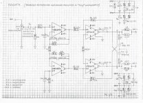
Here is another natural progression. A symmetrical font end.
The is a cct I have been simulating which I call "cirrus" for now.
I will probably try it out soon. It simulates very well with exceptionally low high order distortion.
The LT1010 in the simulation would actually be the LME49600.
Nothing new about the cct, its been done a million times.
Cheers!
Russ
Attachments
Hallo, Mr. Russ,
Nice circuits!
I'm curious to see the simulations at low loads (25-32 Ohm) and
high frequecies...
I like the output stage solution. You think to plan the possibility for others output chip like the more powerful LT1210 or similar types?
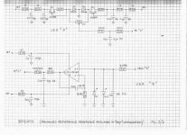
What do You think of my idea for a balanced out headphone amplifier in "SuSy" configuration?
Maybe a contribution for the evolution of Your new circuit?
Regards
semola
Nice circuits!
I'm curious to see the simulations at low loads (25-32 Ohm) and
high frequecies...
I like the output stage solution. You think to plan the possibility for others output chip like the more powerful LT1210 or similar types?
What do You think of my idea for a balanced out headphone amplifier in "SuSy" configuration?
Maybe a contribution for the evolution of Your new circuit?
Regards
semola
Attachments
Hi,
monitoring A and feeding back to C is OK for one side.
Does the cross coupled feedback assure DC servo action for output B?
If not, does the circuit need twin servos?
monitoring A and feeding back to C is OK for one side.
Does the cross coupled feedback assure DC servo action for output B?
If not, does the circuit need twin servos?
Hi, Andrew T,
Right questions! This is what I whish to know......
Someone can help to clarify the mistery?
I prefer the "manual" version since is not a feedback circuit but ,it can work properly in this application?
Regards
semola
Right questions! This is what I whish to know......
Someone can help to clarify the mistery?
I prefer the "manual" version since is not a feedback circuit but ,it can work properly in this application?
Regards
semola
Hey
i am playing around with some SMD layouts of some of your schematics, and i was just wondering if it is ok, if i post them here on the forum?
the first attempt on the diamante can be shown here
http://peecee.dk/upload/view/184036
it isnt finish yet, just to give an impression of what i am doing..
my main reason for doing this is that i hate soldering hole mounted components, and pcb's get so larget compared to smd versions.
and what does CCT stand for?
-Jens
Thanks to a kind soul I just received a set of boards today. So I put a mouser order in for thr basic parts, still need to come up with a power supply. Am ordering some torroidal traffos soon so I need to figure this out any ideas?
Thanks to a kind soul I just received a set of boards today. So I put a mouser order in for thr basic parts, still need to come up with a power supply. Am ordering some torroidal traffos soon so I need to figure this out any ideas?
You'll find good toroidals at cheap price here : http://www.antekinc.com
This one is a 2x15v/50Va, I'm using a 30Va that's more than enough.
Specs here : http://www.antekinc.com/AN-0515.pdf
For the PSU you need a bipolar +/-13v, a little bit more is ok too, max 18v.
Twisted Pear have the LCBPS that will do the job :
http://www.twistedpearaudio.com/power/lcbps.aspx.
Some infos there : http://www.diyaudio.com/forums/showpost.php?p=1614727&postcount=201
Correct me if I'm wrong, I'm a newby 😉
Last edited:
I get all my toroids from AnTek they are great, with great pricing.
Thanks for the links, I am thinking of trying to put together something myself. Any and all info is appreciated. I am trying to wrap my head around the bi-polar concept. I can do a single pretty well using the standard stuff, caps regulator snubbers, etc. and I get the concept...
Thanks for the links, I am thinking of trying to put together something myself. Any and all info is appreciated. I am trying to wrap my head around the bi-polar concept. I can do a single pretty well using the standard stuff, caps regulator snubbers, etc. and I get the concept...
Here's a link to Bipolar PSU using LM317/337 and standards comps, it's in French, schematics are talking all languages :
http://www.sonelec-musique.com/electronique_realisations_alim_sym_001.html
You have all the values to operate at 9, 12, 15 and 18VDC.
Something from the forum, thanks to Salas :
http://www.diyaudio.com/forums/showthread.php?p=1909965#post1909965
Just have a quick search using LM317/337, you'll find good stuff here.
Cheers
Another pair of Diamante's live. Sounding pretty durn good too. Thanks for the boards and design, it's really appreciated. Only been in use for a few hours, I'll let them settle a bit, but as of now the sound stage is good, bass and mids nice and present, highs are not too bright. Very likable noise!!
I am going to be using them as buffers in a basic pre-amp configuration. Does anyone have suggestions for tweaking them for the best sound in this kind of configuration? Remove R26? Unity gain?...
I am going to be using them as buffers in a basic pre-amp configuration. Does anyone have suggestions for tweaking them for the best sound in this kind of configuration? Remove R26? Unity gain?...
rather than convert/switch the Diamante to unity gain try adding a unity gain Follower in parallel to the gain stage and have a separate set of output terminals giving 0dB & +12dB to the two alternatives.
rather than convert/switch the Diamante to unity gain try adding a unity gain Follower in parallel to the gain stage and have a separate set of output terminals giving 0dB & +12dB to the two alternatives.
That sounds like a grand idea, I have puzzled over it and really have no clue how to implement it!
I have an issue with my 4 channel balance build. The offset settles down to 0 (starts -7 mv then slowly settles to 0) Trouble is, when i raise the volume the offset goes all the way up to 0.8v.
any ideas?
any ideas?
Last edited:
- Home
- Amplifiers
- Solid State
- Diamante -a discrete medium power opamp