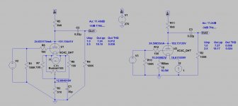
Thanks for that Bela - nice analysis as always. Bela shows the circuit analysis but my schematic was also perfectly clear. Filament bias is different - you have to do a lot more calculations but it's worth it for the sound. Quite a lot of people get confused by it, but it's really quite simple once you "get" it.And there was no clear schematic of the filament-Cathode resistor circuit shown...
Last edited:
When you try it you can say it is good or bad. For your knowlwdge filament bias is quite old. I can certainly say I have seen it for the first time 30 years ago, applied to a DCC90 double triode run with grids and plates in parallel. There are a number of DHTs that run at much lower filament current but it does not mean those are the only choices. In this case, despite the filament current is 1A, running at 15V bias does NOT make it unsafe or difficult at all.Yes BUT - Only in this type of the connection of NON-Floating Filament supply.
You right about that, I didn't try that way, and I never will. Because of too high disipation and hard limit in the Anode voltage that is a must with this way. I tried only Floating regulated DC with CCS module. Own design...
This non-floating way limits the design even for lower filament currents, and for higher filament current of DH power tubes, is almost impossible to achieve safely because of high dissipation... 🙁
.
Still the rest of Your parts of the schematics are not good...
And there was no clear schematic of the filament-Cathode resistor circuit shown...
So far you have no experience with filament bias, you have no experience in running this tube at low current for preamp application (otherwise you would know that distortion is as good as at higher current), you say it is unsafe contrary to real experience where nothing has happened until now etc, etc....
Is there anything useful and objective you can say except criticizing things that you have no idea about? Why are you hijacking a thread where you have nothing to say except the obvious things we all know?
Last edited:
BTW dissipation problem manageable with appropriate -heatsinked- case.
I usually use -chinese- boxes with side heatsinks.
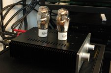
Samples: my #801 preamp
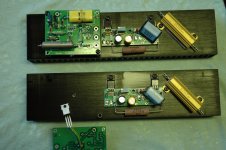
Dissipating parts: filament bias resistor (8R, 1.25A, 10W) , Rod Coleman regulator (4.3W), Ale's gyrator (1.7W).
After 10 hours the side heatsinks about 40C warm.


I usually use -chinese- boxes with side heatsinks.
Samples: my #801 preamp
Dissipating parts: filament bias resistor (8R, 1.25A, 10W) , Rod Coleman regulator (4.3W), Ale's gyrator (1.7W).
After 10 hours the side heatsinks about 40C warm.


Thanks Bela - that looks very nice. Yes, that's the sensible thing to do - put the heatsinks on the side or on the back. I must try that. It looks better than putting them on top of the chassis. You and Thomas Mayer use aluminium body cathode resistors. I must say I preferred the sound of Russian military resistors. I also have a big stock of Dale wirewound resistors I use. They are very easy to mount on the top of the chassis and sound nice. Not quite as good as the Russian ones, though. Lovely build - very nice!BTW dissipation problem manageable with appropriate -heatsinked- case. I usually use -chinese- boxes with side heatsinks.
Samples: my #801 preamp
Dissipating parts: filament bias resistor (8R, 1.25A, 10W) , Rod Coleman regulator (4.3W), Ale's gyrator (1.7W).
After 10 hours the side heatsinks about 40C warm.
Hi,
Long time lurker and greetings from Pattaya.
I have to say this has been a rather frustrating read, and I feel my simple input may help steer this quagmire back to course and away from the personality politics - in my opinion of course.
Filament bias was used in radios as far back as 80 years ago, it's nothing new. Likewise DHT stages, of course. The calculations for setting up a stage uses math that your average 12 year old can do. It's that simple. No special skills, no mystery, no exclusivity, no club membership or faux guru required.
My take on this latest incarnation ? Change Rk to 25 ohm, change Rl to 6k8 and the increase in B+ will pull the Ia close to 20mA, which IMO is a much better place to be.
But this tube has Rp 2k5 and I'd use a 2A3 with Rp at 1/3, but either are sub optimal choices. On paper that is. But if someone prefers it 'as drawn', then so what, all is fine. But if that someone also listens to a system whose LF is limited to 50Hz, and has a stated HF listening deficiency, and also listens to primarily vocal and acoustic music - I would suggest thus 'master tape type sound' needs to be taken with 500g of salt.
Yes, I have built filament bias stages before, yes I can draw one for you, yes it will work - but so what? And that's kinda my point, nothing new or interesting just a twist on a variation.
0
Live and let live.
Edit: I should have written the 'increase to Vp', and not 'B+'. So, 255-260V B+, 125 Vp, -25 Vg, 20mA Ip.
Last edited:
Hello! Thanks for your contributions and the careful thought you have put into this. Always good to welcome a new contributor!Edit: I should have written the 'increase to Vp', and not 'B+'. So, 255-260V B+, 125 Vp, -25 Vg, 20mA Ip.
Lets look at this operating point, with -25V bias. I'm assuming you would use a Rod Coleman regulator for the 6C4C. The V9 needs 3.5V headroom. So the filament supply voltage will be 3.5v plus 6.3V for the filament plus 25V for the bias. That's 35V. So your filament transformer would possibly be a 25V transformer at 1A, though that's not quite enough. But let's say you use that. You want about double the power, so that's a 50VA transformer at 0-25V per valve. That's quite big and you need two. The cathode resistor will be 25 ohms, and since this gets very hot you need double the power so that's a 50W resistor which will have to be metal clad and mounted on a heatsink. The Rod Coleman regulator will also need a quite large heatsink. So be prepared to put a large heatsink on the chassis for the cathode resistors and the regs. You have 2 large filament transformers to house, so where are they going to go? The chassis is already getting quite large now........
I think at this point you may be able to see why I was using around 10V bias. But it's your choice, of course. 25V bias is perfectly possible, just means you will have a large chassis.
I think at this point you may be able to see why I was using around 10V bias. But it's your choice, of course. 25V bias is perfectly possible, just means you will have a large chassis.
Ref circuit at post #82: shows Vg -22V. My comment was to change Rload to 6k8 and increase bias by just 3V.
I assumed you had built it as drawn and therefore had the 30V filament supply.
Ref circuit at post #82: shows Vg -22V. My comment was to change Rload to 6k8 and increase bias by just 3V.
I assumed you had built it as drawn and therefore had the 30V filament supply.
Ah - I see. I think I built that one, but it isn't in filament bias so the filament supply was just for the 6.3V filaments with a cathode bypass cap. It was a driver stage for a 2a3, hence the 470K on the output and the small teflon cap. That one sounded very good, which was why I wanted to update it in filament bias which needs a different operating point. I've never used a 35V filament supply!
Ok.Ah - I see. I think I built that one, but it isn't in filament bias ...
No, all schematics and build descriptions I ever published are all still on my blog for anyone to use freely. With having the responsibility for a tube manufacturing it simply became too much to support DIYers. So I concentrate on finished amps and tube productionHe has deleted most of his DIY stuff from his site, and thinks of himself as a manufacturer
I always preferred thoriated tungsten filaments way before I had my own tube productionThe famous Iron-man has morphed to become the Thoriated-Tungsten-man. 🙂
ELektronenROehren Gesellschaft which could be translated to electron tube company. That was the company name before I took over production. I kept it as the brand name of the tubes but the name of the company is now Deutsche Elektronenröhren Manufaktur GmbHYes he's Mr Elrog now. I wonder where the name came from.
The same for me as well.I always preferred thoriated tungsten filaments ...
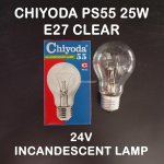
Just a thought, a 25W/24V incandescent light bulb may also be usable there. Nice and bright tungsten filament supporting freedom of DIY guys. 😀... The cathode resistor will be 25 ohms, and since this gets very hot you need double the power so that's a 50W resistor which will have to be metal clad and mounted on a heatsink...
Attachments
I'm not sure that an incandescent lamp will present a stable resistance, for bias purposes.
But I do like the idea of re-using the power!
But I do like the idea of re-using the power!
I've flirted with the idea of using an 845 output stage at lower voltages instead of a 2a3/6C4C. Problem is the filament consumption. 10V at 3,25A is no good in an energy crisis. Same for GM70 which is 20V at 3A. Some of my friends have gone over to solid state like the Pass F4 or MoFo for the output stage. Even those are something like 24V at 1.5A to 2.5A.I always preferred thoriated tungsten filaments way before I had my own tube production
Sad to say, I did not have much success with incandescent lamps as test-loads for filament regulators: the voltage varied much more (for a small change in current) compared to a heating filament.Hopefully stable enough here since typical ΔI is less than 5% for filament bias setup.
- Home
- Amplifiers
- Tubes / Valves
- DHT preamp, 2A3 preamp

