For best temp response of the LND150 CCS pair you need to aim at 500uA ref current so the resistor needs to be adjusted accordingly to the reference voltage you want in the lower JFET
Hi Radu,
It may need some minimum current level, before it regulates, please check that you have some load on the ANODE output when trying it.
Hi Rod,
I have load. Actually, having the 10y in filament bias at 7.5V on 6 ohms, the anode current grows as the voltge grows. It just doesnt regulates.
Hi Ale,For best temp response of the LND150 CCS pair you need to aim at 500uA ref current so the resistor needs to be adjusted accordingly to the reference voltage you want in the lower JFET
That is correct. I used 510k which allows a max of 255V. I am aiming for about 225V, so the CCS is working fine. I read somewhere that in order for the Mosfet and Jfet to work properly, the Vgss mosfet> Vgss jfet. Looked at the datasheets and DN2540 works great with 2SK170, but J310 seems to have a higher Vgss.
Hi Radu,
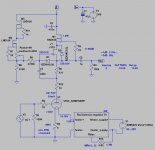
If you can post a quick sketch with your implemented circuit and voltages we may be able to find out. Do you have protection zener across the drain and source of the J310? They may not survive turn on, depending on how gently your HT rises and current is drawn by the load. They don't harm at all but worth adding it. Try replacing both top FET and lower JFET.
cheers
Ale
Thanks Ale. I do have the Zener protection. Took out the J310 and measures fine.
Ill get back with the sketch in a while and Measure the voltages.
Ill get back with the sketch in a while and Measure the voltages.
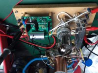
Gyrator board with BF862
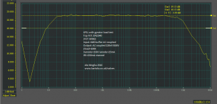
Here is an example with my abused test mule on a 4P1L. You can see the benefits of having a BF862 JFET in the bottom position. Due to its great performance and lower capacitance it performs brilliantly up to 1.5MHz! It also sounds great. The LF response is impacted due to the AC coupling of my measuring gear.
The operating point isn't optimal. I just set it to 25mA, VA=150V, filament bias using Rod Coleman's regulator and filaments staved down to 550mA. The filament resistor is 15R. Just followed my 4P1L stage design in the test mule.
Protection zeners between drain and source are required. BF862 is a sensitive chap and may be damaged during turn on.
Ale
Attachments
What's the B+ and the desired operating point voltage?
B+ is around 300V and the anode is around 228V for 20mA.
Ale,Here is an example with my abused test mule on a 4P1L. You can see the benefits of having a BF862 JFET in the bottom position. Due to its great performance and lower capacitance it performs brilliantly up to 1.5MHz! It also sounds great. The LF response is impacted due to the AC coupling of my measuring gear.
The operating point isn't optimal. I just set it to 25mA, VA=150V, filament bias using Rod Coleman's regulator and filaments staved down to 550mA. The filament resistor is 15R. Just followed my 4P1L stage design in the test mule.
Protection zeners between drain and source are required. BF862 is a sensitive chap and may be damaged during turn on.
Ale
I will try Bf862 before replacing the DN2540, see if it does the same thing.
I thought BF862 is anly good to about 20mA, as its Idss is max 25mA.
Radu
Yes, maximum IDSS is 25mA, hence the operating point on the test mule. As Bela asked, what is the operating point you're aiming at? You will probably need to stick to a J310 for 30mA and above.
If you stick in a DN2540 (TO-92), you said it was working ok, right? If that is the case, I will suspect on the J310. Where did you buy them? I take you are using the TO-92 version and not the latest SMD?
If you stick in a DN2540 (TO-92), you said it was working ok, right? If that is the case, I will suspect on the J310. Where did you buy them? I take you are using the TO-92 version and not the latest SMD?
Indeed, like most of the valves. My "abused" test mule is the gyrator PCB. I made so many modifications on it and is still working!4p1l can take a lot beating and won't mind ������
Attachments
B+ is around 300V and the anode is around 228V for 20mA.
These models (10Y and J310) a little bit different than real ones, so anode current is 25mA. But these old tubes is far from the factory conditions. 🙂
Attachments
Nice.
Bela, I will try to hook in a 10Y for testing. Sorry, I don't have any 801! 🙂
With the BF862 in the board I can do a test on 25mA, should do for a preamp testing example.
Bela, I will try to hook in a 10Y for testing. Sorry, I don't have any 801! 🙂
With the BF862 in the board I can do a test on 25mA, should do for a preamp testing example.
I am testing it now with BF862 at 20mA. It shows 222V B+ and 212V anode. Whatever I do with the B+, anode follows the B+. ther is 2V drop on the Dn and 10V drop on the jfet.
And yes, J310 is to-92 bought on eBay.
And yes, J310 is to-92 bought on eBay.
In January I tested my "last hooked" 10 tube (Sylvania 10, so it older than 10Y ones) with the Ale designed gyrator.
I built same gyrators (IXTP01N100D FET, 200k and 470R resistors), one with NOS TO92 OnSemi J310 -32mA- (I have many OnSemi and Siliconix too, up to 39mA saturation), the other with TO92 DN2540 as "lower" FET.
The B+ was 400V. In my test equipment formerly I was measured about one dozen 10/10Y, and three dozens 801/801a tubes at Ug:-9V, 18mA CCS.
The lab tests was similar, J310 was good up to 30mA, the DN was capable about 60-65ma (the was the upper IXYS FET saturation).
The test equipment bottom noise was at -100dB. The input voltage was 0dBu. In the output don't contains output capacitor, the I measured with 1MOhm input imp. analog voltmeter (VT-176). It has output for soundcard measurement.
The DN spectrum: 0, -67, -75, below -100, -80, below -100, -85, below -100, -85
The J310 spectrum: 0, -69, -77, below -100, -82, below -100, -82, below -100, -83, below -100, -88, -88.
The DN version has less HF rolloff at 96kHz -only 0.2dB-.
The J310 has 0.4dB rolloff at 96kHz.
Both of the measurements has -1dB at 10Hz.
Changed the DN and it works with BF. I must have burned out the DN on the first try.
Now it works like a charm
Now it works like a charm
I lost several DN2540s during development.Whatever I do with the B+, anode follows the B+. ther is 2V drop on the Dn and 10V drop on the jfet.
Now I use 1kV FETs. 🙂
- Home
- Amplifiers
- Tubes / Valves
- DHT line stage 26, 01a or 101d