The three cap route should be taken when the feedback takes off from the switching output stage. In such implementations, the distortion is only low when measured purely differentially across the two legs. Significant distortion products may be present on the common mode output signal. If in a 2-cap filter the two halves are somehow mis-matched (very likely due to tolerances), some of that common mode distortion will show up differentially.
So, in this case, the filter cap should sit between the two inductors with small caps to ground only for some common mode RFI suppression.
In a circuit without feedback, or one which takes feedback after the filter, the 2-cap solution is simplest and works fine. On full bridge UcD circuits I do that.
Note that in either case the filter is undamped in the common mode (ie. there is no resistive load to ground from either leg). This rarely turns out to be a problem though.
The simple 2-coil filter is inefficient on coil material though. A 15uH coil has 0.7 times the number of turns as a 30uH one. So it'll need 0.7 times the amount of ferrite for the same saturation current. Both coils combined contain 1.4 times the amount of material found in a single 30uH coil.
This is solved using a fully differential filter. It uses a 100% coupled inductor with each winding having 1/4 of the inductance you need (since they are coupled, the effective total inductance is 4 times that of one winding). In terms of number of windings and ferrite material this situation is the same as a single inductor. The filter cap is mounted differentially as well. Such a filter is used in the IcePower modules. If you want to attach a sizeable amount of speaker cable you'll need to add a common mode filter after that, but the size of this filter is diminutive. If you want to make an optimal design, the design procedure of a differential + common mode filter is complicated because the leakage inductances will enter into resonances, and the common mode resonant frequency of the CM filter needs to be damped too.
Complexity aside the reason why you don't see differential filters in CE applications is because the mixed quantity diff/comm coil pricing make them more expensive than using too much ferrite on simple filters.
As quantities go up, this situation could change though. One of the more cost-efficient suppliers (TOKO) now have differential coils on offer as well. Do not expect CE goods manufacturers to have them correctly designed though. As the onslaught of seriously substandard but highly sloganesque "digitaru ampurifaia" has shown, the finer details of amplifier design and optimisation are the least of their concerns...
Hi,
Most informative, it seems it was indeed a much more worthy question. Thanks for the excellent reply.
Regarding the CM filter for sizeable amounts of speaker cable, I take it you're talking hundreds of feet, not a dozen? In other words, not a concern for home audio, but a likely requirement for PA systems.
Also I think the circuit I've been working on is as good as "I" can possibly get it, I'm thinking of starting a new thread to post it in however, as it exceeds the original goals of this thread, which was that of a very simple, 100 watt solution.
Regards,
Chris
Hi,
Nevertheless I've been told the current breed of IcePowers is doing acceptably without it, so the necessity of a common mode filter is to be evaluated on a case-by-case basis.
Cheers,
Bruno
In this context, unfortunately, we're talking about a dozen, because the common mode voltage problem is in the tens to hundreds MHz range.classd4sure said:Regarding the CM filter for sizeable amounts of speaker cable, I take it you're talking hundreds of feet, not a dozen?
Nevertheless I've been told the current breed of IcePowers is doing acceptably without it, so the necessity of a common mode filter is to be evaluated on a case-by-case basis.
You mean to say it got a bit complicated but you're getting half a kilowatt out of it? 🙂classd4sure said:Also I think the circuit I've been working on is as good as "I" can possibly get it, I'm thinking of starting a new thread to post it in however, as it exceeds the original goals of this thread, which was that of a very simple, 100 watt solution.
Cheers,
Bruno
Hi,
600+, worked equally well at 1.2Kwatts with 40 volt rails but It would require a few changes to actually use it like that.
It seems I lied, tried to improve on it and now it's... ugly.
OPA637 pspice model Vs OPA637E, E for "enchanced" macro model.. One works, the other, not. Not fluent in spice syntax so I can't see what's changed but I'll figure it out.
Here's some results, as the circuit stood last night.
1 volt input, 1khz, 670 watts output
DC COMPONENT = 6.141836E-05
HARMONIC FREQUENCY FOURIER NORMALIZED PHASE
NORMALIZED
NO (HZ) COMPONENT COMPONENT (DEG) PHASE
(DEG)
1 1.000E+03 5.093E+01 1.000E+00 -7.556E-01
0.000E+00
2 2.000E+03 6.462E-05 1.269E-06 -4.687E+01
-4.536E+01
3 3.000E+03 4.591E-02 9.013E-04 5.057E+00
7.324E+00
4 4.000E+03 1.536E-04 3.016E-06 9.000E+01
9.302E+01
5 5.000E+03 3.640E-02 7.146E-04 -1.764E+02
-1.727E+02
TOTAL HARMONIC DISTORTION = 1.150199E-01 PERCENT
__________________________________________________________
0.1 volt input, 1khz, 7.14 watts output FS~460Khz
DC COMPONENT = 8.112850E-06
HARMONIC FREQUENCY FOURIER NORMALIZED PHASE
NORMALIZED
NO (HZ) COMPONENT COMPONENT (DEG) PHASE
(DEG)
1 1.000E+03 5.064E+00 1.000E+00 -7.577E-01
0.000E+00
2 2.000E+03 4.512E-05 8.911E-06 3.742E+01
3.894E+01
3 3.000E+03 7.372E-03 1.456E-03 1.795E+02
1.818E+02
4 4.000E+03 1.996E-04 3.942E-05 -1.358E+02
-1.328E+02
5 5.000E+03 1.539E-03 3.039E-04 1.759E+02
1.797E+02
TOTAL HARMONIC DISTORTION = 1.487831E-01 PERCENT
________________________________________________________
0.5 Volt input, 1khz, 167 watts output FS= 360~480khz
DC COMPONENT = 5.005389E-05
HARMONIC FREQUENCY FOURIER NORMALIZED PHASE
NORMALIZED
NO (HZ) COMPONENT COMPONENT (DEG) PHASE
(DEG)
1 1.000E+03 2.549E+01 1.000E+00 -7.524E-01
0.000E+00
2 2.000E+03 1.073E-04 4.208E-06 1.241E+02
1.256E+02
3 3.000E+03 1.617E-02 6.343E-04 -1.799E+02
-1.776E+02
4 4.000E+03 5.989E-05 2.350E-06 8.283E+01
8.584E+01
5 5.000E+03 9.033E-03 3.544E-04 -1.795E+02
-1.758E+02
TOTAL HARMONIC DISTORTION = 7.265609E-02 PERCENT
___________________________
20khz 1 volt
DC COMPONENT = -2.850409E-02
HARMONIC FREQUENCY FOURIER NORMALIZED PHASE
NORMALIZED
NO (HZ) COMPONENT COMPONENT (DEG) PHASE
(DEG)
1 2.000E+04 4.966E+01 1.000E+00 -1.488E+01
0.000E+00
2 4.000E+04 6.705E-02 1.350E-03 -1.701E+02
-1.404E+02
3 6.000E+04 1.066E-01 2.147E-03 6.827E+01
1.129E+02
4 8.000E+04 1.065E-01 2.144E-03 7.093E+01
1.305E+02
5 1.000E+05 1.748E-01 3.519E-03 -6.683E+01
7.581E+00
TOTAL HARMONIC DISTORTION = 4.838841E-01 PERCENT
____________
Anyway that will change but it's what I'm working with currently.
Regards,
Chris
You mean to say it got a bit complicated but you're getting half a kilowatt out of it?
600+, worked equally well at 1.2Kwatts with 40 volt rails but It would require a few changes to actually use it like that.
It seems I lied, tried to improve on it and now it's... ugly.
OPA637 pspice model Vs OPA637E, E for "enchanced" macro model.. One works, the other, not. Not fluent in spice syntax so I can't see what's changed but I'll figure it out.
Here's some results, as the circuit stood last night.
1 volt input, 1khz, 670 watts output
DC COMPONENT = 6.141836E-05
HARMONIC FREQUENCY FOURIER NORMALIZED PHASE
NORMALIZED
NO (HZ) COMPONENT COMPONENT (DEG) PHASE
(DEG)
1 1.000E+03 5.093E+01 1.000E+00 -7.556E-01
0.000E+00
2 2.000E+03 6.462E-05 1.269E-06 -4.687E+01
-4.536E+01
3 3.000E+03 4.591E-02 9.013E-04 5.057E+00
7.324E+00
4 4.000E+03 1.536E-04 3.016E-06 9.000E+01
9.302E+01
5 5.000E+03 3.640E-02 7.146E-04 -1.764E+02
-1.727E+02
TOTAL HARMONIC DISTORTION = 1.150199E-01 PERCENT
__________________________________________________________
0.1 volt input, 1khz, 7.14 watts output FS~460Khz
DC COMPONENT = 8.112850E-06
HARMONIC FREQUENCY FOURIER NORMALIZED PHASE
NORMALIZED
NO (HZ) COMPONENT COMPONENT (DEG) PHASE
(DEG)
1 1.000E+03 5.064E+00 1.000E+00 -7.577E-01
0.000E+00
2 2.000E+03 4.512E-05 8.911E-06 3.742E+01
3.894E+01
3 3.000E+03 7.372E-03 1.456E-03 1.795E+02
1.818E+02
4 4.000E+03 1.996E-04 3.942E-05 -1.358E+02
-1.328E+02
5 5.000E+03 1.539E-03 3.039E-04 1.759E+02
1.797E+02
TOTAL HARMONIC DISTORTION = 1.487831E-01 PERCENT
________________________________________________________
0.5 Volt input, 1khz, 167 watts output FS= 360~480khz
DC COMPONENT = 5.005389E-05
HARMONIC FREQUENCY FOURIER NORMALIZED PHASE
NORMALIZED
NO (HZ) COMPONENT COMPONENT (DEG) PHASE
(DEG)
1 1.000E+03 2.549E+01 1.000E+00 -7.524E-01
0.000E+00
2 2.000E+03 1.073E-04 4.208E-06 1.241E+02
1.256E+02
3 3.000E+03 1.617E-02 6.343E-04 -1.799E+02
-1.776E+02
4 4.000E+03 5.989E-05 2.350E-06 8.283E+01
8.584E+01
5 5.000E+03 9.033E-03 3.544E-04 -1.795E+02
-1.758E+02
TOTAL HARMONIC DISTORTION = 7.265609E-02 PERCENT
___________________________
20khz 1 volt
DC COMPONENT = -2.850409E-02
HARMONIC FREQUENCY FOURIER NORMALIZED PHASE
NORMALIZED
NO (HZ) COMPONENT COMPONENT (DEG) PHASE
(DEG)
1 2.000E+04 4.966E+01 1.000E+00 -1.488E+01
0.000E+00
2 4.000E+04 6.705E-02 1.350E-03 -1.701E+02
-1.404E+02
3 6.000E+04 1.066E-01 2.147E-03 6.827E+01
1.129E+02
4 8.000E+04 1.065E-01 2.144E-03 7.093E+01
1.305E+02
5 1.000E+05 1.748E-01 3.519E-03 -6.683E+01
7.581E+00
TOTAL HARMONIC DISTORTION = 4.838841E-01 PERCENT
____________
Anyway that will change but it's what I'm working with currently.
Regards,
Chris
Hi,
Sorry if I misunderstood you - but do you have a working piece of hardware or is it still in a simulation stage?
Cheers,
Bruno
Sorry if I misunderstood you - but do you have a working piece of hardware or is it still in a simulation stage?
Cheers,
Bruno
Hello,
I'm sorry to say.. it's still in the simulation stage, I'll be unable to actually make this myself, for now anyway.
I was thinking if I posted it and someone with some equipment worked out the bugs.. group buy.. who knows?
Regards,
Chris
I'm sorry to say.. it's still in the simulation stage, I'll be unable to actually make this myself, for now anyway.
I was thinking if I posted it and someone with some equipment worked out the bugs.. group buy.. who knows?
Regards,
Chris
If "exotic" parts are hard to come by, I'd most certainly recommend trying to make a lower power amp work first. Making a kilowatt amp as your first (or your second for that matter) project is likely to become a source of frustration. Real life amps suffer from a whole set of parasitics that don't show up in a simulation (e.g. anything to do with circuit lay-out). This apart from the fact that spice generally sux at simulating switching stuff.
Parasitic-related problems grow with output power. If you build a 25W amp (or 100W in full-bridge), you're unlikely to run into the stickier ones, even with less than optimal component choice (important if you have trouble getting parts). The likelihood of having a working one the first time round is healthy.
A kilowatt amp on the other hand is certain to show you every corner of the parasitics department before it'll play, let alone put out the distortion figure promised by spice.
Cheers,
Bruno
Hi Chris,
rely on Bruno, I made some of these experiences with my very few (different, not only class-D) switching stage projects well below 50W. After learning these many effects in the practice, you'll find some explanations in the literature or appnotes, unfortunately not before, at least in my case.
When I tried to model parasitics in the switching stages and used better (=big) models, I figured out PSpice's limits fast (e.g. stability). Try to compare LTSpice with PSpice.
Nevertheless I read your posts very interested and wish you success in your project. May we see a schematic sometimes (Pspice exported to pdf or gif or itself)?
Regards, Timo
Now that sounds very familiar😀tiki said:After learning these many effects in the practice, you'll find some explanations in the literature or appnotes, unfortunately not before, at least in my case.
Also, note "some" explanations...
Hi,
Yeah, I realise that, certainly after cooking ~10 mosfets and a bjt on a ~30 watt version. (not bad with no scope though 🙂 and a plastic protoboard no less)
I personally wouldn't try a low power version, then a mid power version.. etc.
I see no reason why one couldn't limit the current on the power supply, start off with half an amp, if there's no smoke, step it up another half an amp, work out any new bugs that show along the way, until you've got it working fine at full power, and then make a revised pcb with the options you've selected, and start the whole process over again! Might save some time and money that way.
Working out parasitics in Spice is problematic I think, more like a waste of time. How can you account for every possible real world interaction? On top of that, all versions of spice aren't capable of realistically modelling all aspects of a part. Mosfets being a prime example, with dynamic gate resistance not being modelled, reverse recovery... etc. So to be meaningfull I think one would need both a real circuit to work with, and good equipment. For those reasons, I both, dont' intend on trying this with LTspice, or attempt to make it myself, as again, it would simply be foolish without the equipment required.
So basically, my roll in this project is comming to an end, having taken it as far as I'm able to, I will be posting simulation results, schematics, everything. I'll also look into exporting the schematic in a better method than my usual screenshots which are rather poor.
Everyone is most welcome to pick it up where I left off, and I hope they do.
Throughout this project I've tried to use good parts which will do the job properly, yet nothing considered exotic by any means, for at least to the best of my knowledge, free samples can be obtained for just about everything I've used.
Because spice doesn't model mosfets realistically, it still uses IRF540 mosfets, I would not recommend actually using them in this circuit, but rather a mosfet with much higher current capability, with gate charge less than 100nC, and a good charge ratio. I guess the reverse recovery aspect comes down to a trial and error/hit or miss situation.
Also, whenever I ran into convergance errors, instead of changing the simulations options drastically, I changed the part values.
For example the value of the balance resistor is tricky, if you achieve too good a balance, it won't converge no matter what, so instead of changing reltol to 1 to force it to converge, I threw off the balance by changing the value slightly. Real world, that would never be a problem.
I'd say it paid off, the circuit now simulates fine using all standard preset simulation options (ITL4=10) so there's no tricks used in that respect and I hope no one will have a problem simulating it themselves.
You'll see everything I have to offer very soon, I'm still playing around with a few things.
One little trick I've found, incedently, is to bias the ops amps used into class A by adding a resistor from the Vee to the output. I've read on this very forum, and others, that it can really improve the sound of them. It has also improved simulation results. So I will leave that change in, but it's an option to be experimented with, perhaps.
Regards,
Chris
Hi Chris,
If you use a protoboard like this, an oscilloscope would be very useful, because the protoboard with its connector matrix (better: mesh) adds huge amounts of capacitances, inductances and unpredictable contact resistances, especially, if you want to work on the next day. My next step was this breadboard. Here i could confirm the rule of several nH per cm wire length very easily by "surfing" with the oscilloscope tip on the gate wires.
Therefore I believe JohnW's statement another time, that a _good_ layout is the half of the solution. Unfortunately only the second one.
Thank you for your diligent and interesting work.
I'm very busy with the Uni-project, Orcad annoys me everyday. And the switching output stage is only a little part of it. For my own loudspeaker project I switched to the UcDs. I cannot make it better than Bruno or JohnW.😡
Bruno and John, yesterday I read over this thread, I wonder how you find the time for these activities. It's always diverting and very instructive to follow your discussions. many Thanks again for your interesting posts, they are an invaluable contribution to this forum.
The spare time stories are interesting also, you were lucky in Belgium, not to be roped in. I can feel with you.
Best regards, Timo
Yes, cooking is easy in that way...Yeah, I realise that, certainly after cooking ~10 mosfets and a bjt on a ~30 watt version. (not bad with no scope though and a plastic protoboard no less)
If you use a protoboard like this, an oscilloscope would be very useful, because the protoboard with its connector matrix (better: mesh) adds huge amounts of capacitances, inductances and unpredictable contact resistances, especially, if you want to work on the next day. My next step was this breadboard. Here i could confirm the rule of several nH per cm wire length very easily by "surfing" with the oscilloscope tip on the gate wires.
Therefore I believe JohnW's statement another time, that a _good_ layout is the half of the solution. Unfortunately only the second one.
Couldn't we read anywhere to use Fets with gate charges lower than 20nC?with gate charge less than 100nC
Good idea, to bring them out of takeover distortions.to bias the ops amps used into class A by adding a resistor from the Vee to the output
Thank you for your diligent and interesting work.
I'm very busy with the Uni-project, Orcad annoys me everyday. And the switching output stage is only a little part of it. For my own loudspeaker project I switched to the UcDs. I cannot make it better than Bruno or JohnW.😡
Bruno and John, yesterday I read over this thread, I wonder how you find the time for these activities. It's always diverting and very instructive to follow your discussions. many Thanks again for your interesting posts, they are an invaluable contribution to this forum.
The spare time stories are interesting also, you were lucky in Belgium, not to be roped in. I can feel with you.
Best regards, Timo
Hi Timo,
I think had I an oscilloscope I wouldn't be playing with a breadboard like that. I really enjoyed seeing your second version, that's not a method I've ever seen. Kind of do it yourself SMD huh? Looking at it though I can't really see how it works, trace wise.
I don't think I could make it "better", but I do think I could make it, and make it quite good at that, considering all the help, tips, etc.
My intention was to kill some time productively🙂
My simulation results are showing a disadvantage to biasing the op amps in class A, but only with input levels so low that it doesn't really amplify at all anyway, in the milli watt range. After that, there's a clear advantage right up to full power.
I've recently improved my simulations remarkably, which is nice because it shows some real potential, on the other hand, it's not entirely useful either, but hopefully it might entice some to give it a try.
Anyway, I have cleaned up the circuit, I know how to get a decent image out of it as well, I plan on tweaking no more values nor making any changes to it. It's a done deal. You'll all see it in about a day, as I'm still simulating.
Regarding the gate charge, .01nC would be great, I just meant, I wouldn't go over 100nC, as it gets ugly with this driver, from what I can see anyway.
For now, here's a hint of what's to come.
1V @ 20Khz, 748W,
DC COMPONENT = -3.041378E-03
TOTAL HARMONIC DISTORTION = 7.036225E-01 PERCENT
TOTAL POWER DISSIPATION 2.31E+00 WATTS
__________________________________________________
1V @ 1Khz (5 harmonics) ~816W
DC COMPONENT = 1.322911E-04
TOTAL HARMONIC DISTORTION = 2.318553E-01 PERCENT
TOTAL POWER DISSIPATION 2.31E+00 WATTS
__________________________________________________
100mV at 20Khz, ~8W,
Fs~480Khz
DC COMPONENT = 2.060138E-04
TOTAL HARMONIC DISTORTION = 1.308603E-02 PERCENT
TOTAL POWER DISSIPATION 2.31E+00 WATTS
... even though it's only 30V rails, this amp would love a 1000VA transformer.
I think I'll be posting it all tomorrow, Class ucD FB ref design 😀
Cheers,
chris
And no change of power dissipation versus output power or frequency. Surely something is fishy here?
Hi Chris,
I guess your talking about a full HBridge & +/- 30V but 750W!, what load are you intinding to drive - A directly coupled Ribbon Speaker 🙂
It be very interesting to see how close the Sim results are to the real Hardware.... I'm betting you could land a 747 between them!
Keep up the good work 🙂
John
I guess your talking about a full HBridge & +/- 30V but 750W!, what load are you intinding to drive - A directly coupled Ribbon Speaker 🙂
It be very interesting to see how close the Sim results are to the real Hardware.... I'm betting you could land a 747 between them!
Keep up the good work 🙂
John
Hi,
Ok....... OOOOOk ...... you guys got me... I don't really have a circuit at all... it was all a fabrication.. I.. I can't get it to converge.. heh heh.
I see it's pick on Chris day 😀
That's alright, I can take it!
Nothing is wrong, theoretically it should be 100% efficient. Add to that a bit of slew rate on the mosfets and I guess you get 99% efficiency.
Why should it change? The rate of change of the mosfets as they switch stay's the same regardless of what frequency it's modulating at, and the pwm frequency is basically centered on 480Khz, it doesn't vary from 100khz to 1Mhz.. as they switch states being the only part where they dissipate power, it stays fairly constant, as it should.
Fishy?? Spice "could" be lying to me, during my simulations I've noticed results changing for the very same simulation, not by a great deal, but I noticed! So.. I've rebooted and I will redo them all today. I don't expect they'll change much at all, but it will be done.
Hi,
I sure am talking about that. Do you think 750W is not possible?
Unless I'm wrong (always a strong possibility)
Working with a 4 ohm load, (that's what my speakers are)
30V/4ohm=7.5amps. Now make that a full bridge... 60Volts*15amps= 900 watts.
Now if you build a power supply accordingly, 1000VA transformer let's say... what's the problem?
In summation, aside from the power of it, which I think it should be able to do, c'mon guys.... this IS spice, not tektronix and AP2.
Regards,
Chris
Ok....... OOOOOk ...... you guys got me... I don't really have a circuit at all... it was all a fabrication.. I.. I can't get it to converge.. heh heh.
I see it's pick on Chris day 😀
That's alright, I can take it!
Hi,
(816W-2.31W)/816W*100 = 99.7% efficiency?
What's wrong?
Timo
Nothing is wrong, theoretically it should be 100% efficient. Add to that a bit of slew rate on the mosfets and I guess you get 99% efficiency.
And no change of power dissipation versus output power or frequency. Surely something is fishy here?
Why should it change? The rate of change of the mosfets as they switch stay's the same regardless of what frequency it's modulating at, and the pwm frequency is basically centered on 480Khz, it doesn't vary from 100khz to 1Mhz.. as they switch states being the only part where they dissipate power, it stays fairly constant, as it should.
Fishy?? Spice "could" be lying to me, during my simulations I've noticed results changing for the very same simulation, not by a great deal, but I noticed! So.. I've rebooted and I will redo them all today. I don't expect they'll change much at all, but it will be done.
Hi Chris,
I guess your talking about a full HBridge & +/- 30V but 750W!, what load are you intinding to drive - A directly coupled Ribbon Speaker
It be very interesting to see how close the Sim results are to the real Hardware.... I'm betting you could land a 747 between them!
Keep up the good work
John
Hi,
I sure am talking about that. Do you think 750W is not possible?
Unless I'm wrong (always a strong possibility)
Working with a 4 ohm load, (that's what my speakers are)
30V/4ohm=7.5amps. Now make that a full bridge... 60Volts*15amps= 900 watts.
Now if you build a power supply accordingly, 1000VA transformer let's say... what's the problem?
In summation, aside from the power of it, which I think it should be able to do, c'mon guys.... this IS spice, not tektronix and AP2.
Regards,
Chris
Hi Chris,
(60V/sqrt(2))^2/4Ohm=450W!
But only without any losses (Rdson, Ri(supply)...).
Anyway, your work is worth to be done, this should be a hint only. I'm still curious...
Best regards,
Timo
Spice _will_ tell you:Working with a 4 ohm load, (that's what my speakers are) 30V/4ohm=7.5amps. Now make that a full bridge... 60Volts*15amps= 900 watts.
(60V/sqrt(2))^2/4Ohm=450W!
But only without any losses (Rdson, Ri(supply)...).
Anyway, your work is worth to be done, this should be a hint only. I'm still curious...
Best regards,
Timo
Hi Timo,
I don't get that equation.
The few references I've found show that math I did as correct, and spice backs it up. Have a look. 1.2Volts input would be about max, that's at 1 volt, at 1.2Volts input it's fine at 20khz but just clips at 1khz.
Looks like a bit more than 450 though, it makes sense to me.
Regards,
Chris
Attachments

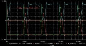
Hi,
One more, showing some extreme behavior.
1.2Volt input at 10Khz, square wave, 90% duty ratio.
Do you really think spice is off by that much? I really don't, but I wouldn't expect you'd ever see that kind of power, if you build it with a wimpy 200VA transformer either, which is why I'd recommend 1000VA.
Output and input voltage has been scaled for your viewing pleasure. Output voltage is actually at -58.5volts, so it's not clipping yet.
In this case:
TOTAL POWER DISSIPATION 8.79E+02 WATTS
Regards,
Chris
Attachments

- Status
- Not open for further replies.
- Home
- Amplifiers
- Class D
- Development of a "reference" class D starting point