Hi,
I hear ya! .. "but" without the proper test equipment I see no point taking it to that extent.
My protoversion is as simple as it gets, gain of 10 to avoid any chance at clipping, it had a limitting circuit on the input, which I've found was safe to take out, mostly after I put 100uf bootstrap electro. that was bypassed by a ceramic..
No input op amp differential stage....nothing.. hand wound air core..
Heck, I'd love to build my fully differential full bridge version at 500 watts too, all good components.. I won't do it without a scope. So it looks like it's a module in my future
Jan-Peter said:Come on guys, please start with the PCB layout!
You can't make a Class-D proto by point to point wiring.
One layer with a big groundplane and on the other layer the rest of the electronics.
Regards,
Jan-Peter
www.hypex.nl
Hi,
Wanna bet? My proto is only about 10 to 20% p2p at that.
It's about 40Watts and it works. I'm amazed it does work at all, let alone this good. I certainly would not call it HI-FI though, or a reference design, or wasted effort.
Anyway, on a more serious note;
Johan was nice enough to try and make a PCB design, asked for feedback on it, twice, and got none at all.. maybe it would progress better if had.
classd4sure said:
Hi,
Wanna bet? My proto is only about 10 to 20% p2p at that.
It's about 40Watts and it works. I'm amazed it does work at all, let alone this good. I certainly would not call it HI-FI though, or a reference design, or wasted effort.
Anyway, on a more serious note;
Johan was nice enough to try and make a PCB design, asked for feedback on it, twice, and got none at all.. maybe it would progress better if had.
Hi All!
Chris,
If you send me your schematic I'll try to design a PCB for it. I'll post it here and anyone can make suggestions where and what to change on it. I think I'm going to post the gerber files...
Best regards, lkadar.
PS.: sorry for my bad English...
lkadar said:
Hi All!
Chris,
If you send me your schematic I'll try to design a PCB for it. I'll post it here and anyone can make suggestions where and what to change on it. I think I'm going to post the gerber files...
Best regards, lkadar.
PS.: sorry for my bad English...
Hi,
Works for me! I'll be posting them soon, I hope, it's still a work in progress at this point as there's a few things I want to try. Won't be long before you see it though.
Thanks,
Chris
Hi,
Just had a question about the same old beaten up topic of emitter resistors in the comparator outputs.. as seen in post #410.
It's been said only 2 resistors are required, I've been thinking about that.
If two would work, why not 1?
would 2 or 1 work though?
Let's say one gets hot, current through it increases, so voltage over the resistor increases providing greater amounts of feedback and limiting the current through it, allowing it to cool down and stop the hogging situation.
So if any two transistors should share a resistor, I'm unable to see those two compensating properly. If one starts to run away the voltage over the resistor will increase, but that will limit the current on the cooler transistors as well, keeping one hotter than the other and wanting to hog the current.
I think using one resistor for all four would amplify this situation.
So unless someone tells me otherwise, I'm going to use four in order to keep each transistor properly compensated.
You don't use one resistor for all four, but one resistor for each pair. Only one of the pairs have their emitters tied to the bases of the balance as in the HB circuit.
You could try offsetting the error using extra emitter degeneration on the transistors that drive the high sides, but it sounds like half a solution to me.
Now, seriously, how do you make sure the transistors all dissipate the same power? You know that on average, they'll all be conducting the same current. There's something else to power apart from current. See if you can get that to be equal too, possibly moving the dissipation to somewhere it won't hurt.
There's something else to power apart from current. See if you can get that to be equal too, possibly moving the dissipation to somewhere it won't hurt.
Yeah.....
I agree it's half a solution... the other half being the monolithic IC 😀
Seriously though, I'm not much of a "designer" and it took a fair bit of research for me.
So far I've come up with something for which a..perhaps too simple.. implementation seems to work great.
I've only tested it on a half bridge version thus far..
+-50 volt rails the output going to the lower side driver has about 800mv switching across it at a DC offset of say 11 volts, and the high side driver has about ~510mv across it at the peaks, about ground. While the..area I unloaded it to has about 98 volts across it.
Close enough.. am I in the ball park now?
For the half bridge it's only 1 extra transistor in cascode to provide a level shift.
classd4sure said:
For the half bridge it's only 1 extra transistor in cascode to provide a level shift.
!!
...hadn't thought of doing that only to the HS level shift transistor... I did 'em both, for symmetry's sake. Another cost cutting option there...
Yep, that's my next step actually, for the same reason, I don't like the DC offset on the low side..
Right on!~ Almost done I think. 🙂
Right on!~ Almost done I think. 🙂
classd4sure,
I think you did well in figuring out the cascode. You are definitely getting there. 🙂
I think you did well in figuring out the cascode. You are definitely getting there. 🙂
subwo1 said:classd4sure,
I think you did well in figuring out the cascode. You are definitely getting there. 🙂
Thanks Subwo1! Makes my day.
After a few hours of researching I came up with the cascode, a few days ago, but held back on trying it out, doubting my ability, Bruno's post gave me a bit of a shove, lesson learned, try first, doubt later.
He was wrong about one thing though, I'm not banging my head on the desk at all, as I'm rather proud of myself for having worked it out. I'm glad no one spit out the solution.
I have since tested the half bridge with a cascode arrangment on the low side driver's comparator output as well and they are now perfectly symmetrical which I like alot more.
Right now I think I'm going to fire up my plastic proto-board amp and annoy the neighbors.
It's funny, I cooked all my nice fairchild sample fets on it and the fets I can't kill were taken from a failed monitor.. irf630's, soldered new legs on em... tough little suckers, they really take a good beating.
Hello,
Should I care if a BJT that's used as a switch is a low noise type?
Also, would it matter if the transistors in a cascode configuration are different?
I think the answers would be, no and yes?
As I'm not sure if I can keep the Mat-04 or not, would be nice if I could though.
Thanks
Should I care if a BJT that's used as a switch is a low noise type?
Also, would it matter if the transistors in a cascode configuration are different?
I think the answers would be, no and yes?
As I'm not sure if I can keep the Mat-04 or not, would be nice if I could though.
Thanks
The balance pair has an impact on noise if they have no emitter resistors.
The switch pair(s) have no impact on noise.
The transistors for the cascodes are chosen for their merit in this configuration and are most likely different from the balance/switch transistors. They need not be matched at all.
The switch pair(s) have no impact on noise.
The transistors for the cascodes are chosen for their merit in this configuration and are most likely different from the balance/switch transistors. They need not be matched at all.
Hi Bruno,
Well that is good news, thanks!
I'll then keep the MAT-04 both for thermal matching (can't hurt) but mostly for the space savings.
Regards.
Well that is good news, thanks!
I'll then keep the MAT-04 both for thermal matching (can't hurt) but mostly for the space savings.
Regards.
Couldn't Help it..
Hi,
Just a few a bit of junk I thought I'd share..
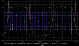
Earlier today I saw Jan-Peter mention having seen a 10khz square wave put through a UCD and I thought.. Neat! I wonder..
Here we have it, 1 volt input 10khz square wave.
Spice impressed me today.
Hi,
Just a few a bit of junk I thought I'd share..
Earlier today I saw Jan-Peter mention having seen a 10khz square wave put through a UCD and I thought.. Neat! I wonder..
Here we have it, 1 volt input 10khz square wave.
Spice impressed me today.
Attachments
Hi,
Jan-Peter, thanks for letting me know it's on par with the real deal.
Bruno, how about using diodes for providing the feedback for the balance pair instead of resistors? Seems to work OK, any down side? I was thinking it might make it easier to tune certain values as they'd be more independant of each other.
Thanks.
HMmm yeah I realise now that was indeed a silly question, just needed some sleep! The voltage over a diode wont' be a function of the current through it which would be a requirement for noise reduction I think.
Heh yeah, but ya did anyway 🙂
Here's a possibly better question for you.
Full bridge filter configuration:
There's two possibilities that I've seen, one is the two cap to ground configuration, the other is a three cap configuration, the third being parallel to the load.
Which is best? I've read the two cap config is best at common mode cancellation, I've seen no "pro's" ever listed to the three cap config, and yet every actual circuit example I've seen uses it.
What's your take on that?
- Status
- Not open for further replies.
- Home
- Amplifiers
- Class D
- Development of a "reference" class D starting point