Hi
I made something like that as short circuit protection, if i understand your explanation good (but not with fets but npn and pnp).
I had between a power supply rail and a fet a sense resistor.
Over this resistor was a npn placed (base and emittor).
When this npn was activated (thanks to voltage drop over the resistor at overcurrent), it activated on his turn a pnp which pulled the voltage on the cap of the astable multivibrator to ground, so that the oscilation process was disturbed.
Then i tried to use the same principle (pulling down the voltage on the cap), to act as a mute but the result was a huge pop, even worse than the pop when i startup and shutdown the amp.
So instead of pulling to ground i tried pulling to 5V.
This gave a smaller pop but still unacceptable, or am i just very demanding?
Can you give a bit more information about how i can use your circuit to avoid "start and stop popping"?
You know, you all are probably very experienced engineers, i'm just a student who still has to learn muuuuuch 🙂
Maybe i'm wrong, but after all, the intention to avoid popping is to make sure that the comparator is "disabled" during startup and shutdown of the powersupply, isn't it?
Anybody with the same opinion? I have no idea about that 🙁
Maybe i can test it when i make a little circuit with the lm311 and then activate the strobe pin, something like an astable multivibrator with 3 resistors and 1 cap, and then measure the output when the strobe is activated.
Greetz
Bart
If memory serves me, there was an input buffer feeding the comparator, having a very elegant N channel pull down as a "Mute" feature at the input of the buffer. Could this serve your purpose as well?
I made something like that as short circuit protection, if i understand your explanation good (but not with fets but npn and pnp).
I had between a power supply rail and a fet a sense resistor.
Over this resistor was a npn placed (base and emittor).
When this npn was activated (thanks to voltage drop over the resistor at overcurrent), it activated on his turn a pnp which pulled the voltage on the cap of the astable multivibrator to ground, so that the oscilation process was disturbed.
Then i tried to use the same principle (pulling down the voltage on the cap), to act as a mute but the result was a huge pop, even worse than the pop when i startup and shutdown the amp.
So instead of pulling to ground i tried pulling to 5V.
This gave a smaller pop but still unacceptable, or am i just very demanding?
Can you give a bit more information about how i can use your circuit to avoid "start and stop popping"?
You know, you all are probably very experienced engineers, i'm just a student who still has to learn muuuuuch 🙂
Maybe i'm wrong, but after all, the intention to avoid popping is to make sure that the comparator is "disabled" during startup and shutdown of the powersupply, isn't it?
IMHO, pulling down the strobe pin gives you maximal DC on output, of course, if am i correctly imagine your driver.
Anybody with the same opinion? I have no idea about that 🙁
Maybe i can test it when i make a little circuit with the lm311 and then activate the strobe pin, something like an astable multivibrator with 3 resistors and 1 cap, and then measure the output when the strobe is activated.
Greetz
Bart
Hi, I'm far too burnt to think at all now, but if you want zero popping you could always throw in a relay after the output.. disconnect the load. Supposedly that's a tricky circuit to control.
The N channel I saw was nothing so complex, just pull the gate high, signal goes active low, bringing input of the buffer to ground level. I'd think leaving the output to oscillate at 50% duty cycle. I think from what I've read for certain op amps the strobe pin enables the output, clocking it, the data sheet should provide the best info on it though. Sorry I can't help ya more than that. Why not try some of the UCD circuits in this thread? Far improved circuit, easier to control.. etc. Pay off might be worth it if you have the time for it.
Regards,
Chris
I will try a ucd in the future.
I'm aware of all his advantages in contrast to soda.
But i'm still in a reading and learning stage.
So i should say, keep up the good work here 🙂
Greetz
Bart
I'm aware of all his advantages in contrast to soda.
But i'm still in a reading and learning stage.
So i should say, keep up the good work here 🙂
Greetz
Bart
Re: Removing the squeak and the pop ...
I may be off base here, but how about coming from somewhat the other direction and insure that the all the low voltage circuitry is up and running at 50% duty cycle before powering the output stage? Just a thought.
el burto said:Hello
Now you know, there is no discrete comparator in soda.
Thats why i wanna ask, can i use the "strobe" pin on the LM311 to solve the problem?
I thought so because the datasheet told me that u can disable the output with the strobe pin.
So can i avoid a squeak and a pop with using the strobe pin? And if someone maybe knows how, can you tell it?
What you people think about this?
A little picture of the "strobe configuration" in the next datasheet on the first page:
http://cache.national.com/ds/LM/LM111.pdf
Greetz
Bart
I may be off base here, but how about coming from somewhat the other direction and insure that the all the low voltage circuitry is up and running at 50% duty cycle before powering the output stage? Just a thought.
Hi,
That's a good thought to be certain, but in this circuit oscillation is caused from the feedback which is taken after the bridge so I don't think that would be possible. Seems Bruno wasn't kidding when he said it was "tricky". I'm not even sure if the "mute" idea would stop the mentioned squeek & pop, since the most that would do is provide the 50% duty cycle, I don't think you can actually disable the bridge though. Might have to live with the squeek /pop. I don't know.
It is interesting though. The only way I can think of is an output relay to disconnect the load.
Then again, this might be good cause to ditch that output stage and go with a dual N channel + good driver IC with it's own disable! Problem solved.
I wonder if it would be possible to add an N channel active pull down "mute" on the actual output, instead of a relay, could that work?
It may be possible to shunt the output to ground for a few milliseconds by connecting two mosfets back to back and then use an optocoupler to provide gate enhancement of both gates wrt sources for a short time. Hopefully the output choke would protect the switching MOSFETS from the current surge for long enough.
Or alternately, and maybe better, use the back to back MOSFETS as a solid state relay. Then the gates could be enhanced after the initial circuit start-up. They could then be enlisted in the double-duty of providing speaker protection in case of circuit malfunction. Also this way, the gate power supply would not have to be supplied to the MOSFETS prior to circuit start-up. I wonder if a standard solid state relay would work even better, though they respond slower, since they may not need an internal floating gate power supply given that they may be gate-enhanced by internal photocells. The solid state relay would maybe work better in the above case, too.
Or alternately, and maybe better, use the back to back MOSFETS as a solid state relay. Then the gates could be enhanced after the initial circuit start-up. They could then be enlisted in the double-duty of providing speaker protection in case of circuit malfunction. Also this way, the gate power supply would not have to be supplied to the MOSFETS prior to circuit start-up. I wonder if a standard solid state relay would work even better, though they respond slower, since they may not need an internal floating gate power supply given that they may be gate-enhanced by internal photocells. The solid state relay would maybe work better in the above case, too.
I have used a relay on the outputs of my amplifiers for several years. It was rated for 10A, with pretty low nominal contact impedance. Nevertheless, my amplifier circuits didn't start to "sing" and "rock" heavily until I made a try without the relay. My conclusion: you want as little as possible between the amplifier outputs and the speakers 🙂 (if you're at all concerned with sound quality)classd4sure said:The only way I can think of is an output relay to disconnect the load.
The way I'm currently doing it is with a relay between the HV power supply and the amplifier cards, which only have minimal capacitor reservoirs for decoupling needs. And across that relay I have power resistors providing startup-current to my amplifier circuits. So if anything goes wrong, the relay will shut off main power, but some current can still go through the resistors. I have small pops and squirks when I turn on and off the amp.
This is not an optimal solution, so I'm aiming for improvements in future circuits.
Hi everyone,
Chris and I have been doing some off-line collaboration to figure out how to do a full-bridge output with the UcD circuit.
One obvious alternative is to build two complete UcD single-ended circuits, and then connect them in a bridge configuration (invert the input on one of them if you don't have a balanced signal source), and add the small capacitor between the outputs to make them align their oscillation frequencies as Bruno suggested.
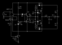
The other alternative, which could save some components and space, is the circuit I'm attaching here. Credit goes to Chris for figuring out how to make quadruple outputs from the comparator.
We have one question about this scheme though; it didn't work well in the simulation until we lowered the value of the common base resistor to Vss in the comparator to a very low value (R45=10 ohms in my schematic). There might be an issue with sharing the bias current through the comparator between two output transistors simultaneously? Do we run the risk of current-hogging in real life with this type of configuration?
Bruno, could you perhaps comment on this when you get back?
Chris and I have been doing some off-line collaboration to figure out how to do a full-bridge output with the UcD circuit.
One obvious alternative is to build two complete UcD single-ended circuits, and then connect them in a bridge configuration (invert the input on one of them if you don't have a balanced signal source), and add the small capacitor between the outputs to make them align their oscillation frequencies as Bruno suggested.
The other alternative, which could save some components and space, is the circuit I'm attaching here. Credit goes to Chris for figuring out how to make quadruple outputs from the comparator.
We have one question about this scheme though; it didn't work well in the simulation until we lowered the value of the common base resistor to Vss in the comparator to a very low value (R45=10 ohms in my schematic). There might be an issue with sharing the bias current through the comparator between two output transistors simultaneously? Do we run the risk of current-hogging in real life with this type of configuration?
Bruno, could you perhaps comment on this when you get back?
Hi,
Seems to be a bit of a lack of interest here these days. Does anyone care about a full bridge Ref design? I've another version, Johan is making a PCB layout... ETC. How about some feedback? It's alot less work to only make provisions for a half bridge, so if there's no demand for it.. ya might not get it. Let us know.
Regards,
Chris
Hi
I'd be interested in a full bridge version. More power from the same supply voltage and no worries wrt power supply pumping
Feel a bit guilty for asking as I haven't added anything to this thread, mainly because a lot of stuff went straight over my head. I need a 'class D /How to drive mosfets for dummies' book
Mark
Hi everyone!
Attached is a draft of a differential full-bridge UcD circuit with LAG-filters. Note that no component values are filled in yet, so you will have to compare this with the circuits we have been discussing here previously. You need Eagle 4.11 or later to review the files.
Of course, one doesn't have to build the full bridge; I could make a stripped down version later when the function of this full version has been verified.
There are only a few air-wires needed, for the comparator-to-driver signals, and for the feedback from the output-via-filters to the inputs.
Power supply voltages and ground are intended to be connected separately to the "modulator part" and the "driver+output" parts. Also, one can choose to have voltage-regulators on-board for the supply to the OP-amp, or one could have such regulation in the central power supply.
Please help me review this, in particular a sanity check of the schematic versus previously discussed simulated/prototyped circuits would be great. (No point in building something that can't work at all 🙂)
Don't hesitate to ask if anything is unclear.
Furthermore, I think I have come up with a tentative "home" for this project - on the diyaudio.com WIKI! Check out this UcD-clone-page 😎.
Of course, this becomes what we collectively make of it. (Or rather, it depends on who contributes to it!) It could be made to contain sections on the various subjects we have been discussing, like how to make a DIY output inductor for high-power class D amps, and how to select/drive mosfets, and so on...
Attachments
Hi Johan,
I can't open your *.sch file in any version of orcad I have, just get a file i/o error, can you again include a screenshot please. I intended on posting mine in a few days (been busy), but if it's anything like it I wont' bother. Waiting on some transistors before I can power up my breadboard version.
Regards,
Chris
Hi again,
I opened the .sch file in notepad and found they're both eagle files. Silly me. Anyway I hope you get some feedback on that, it wont' be comming from me.
Regards,
Chris
I opened the .sch file in notepad and found they're both eagle files. Silly me. Anyway I hope you get some feedback on that, it wont' be comming from me.
Regards,
Chris
Hi Johan,
I tried to open the files but I got the message that I need to enter the license key. And I thought I had the free version.
I tried to open the files but I got the message that I need to enter the license key. And I thought I had the free version.
That is very strange! I have made this with the Freeware version myself. I did install the freeware license which came with the download in order to avoid the initial dialog every time, but that's all. Beyond that, I can't think of anything to help you...subwo1 said:I tried to open the files but I got the message that I need to enter the license key. And I thought I had the free version.
That thought probably covers it. Maybe the record of the license was lost from my system after my XP OS melted down and I had to re-install it.  I can try re-installing the Eagle software.
I can try re-installing the Eagle software.I wanted to built self oscilating classD. What core material is for the final choke? Ferrites? Iron core? KoolMu?
Ferrites!What core material is for the final choke?
BTW, Guys, what you think about using sample accessible $10 tda8927 + .4$ lm319 like alternative DIY UcD reference design..
some fastfood concept? Dead time are 70ns, is not so bad?
- Status
- Not open for further replies.
- Home
- Amplifiers
- Class D
- Development of a "reference" class D starting point