Don't forget 10Y "brother": 801/801a/VT-62.
The "first serial" 801 very good, the graphite anode versions are "seductive" for using in preamp.
p.s.
The more robust 801a/VT-62 series tubes are performs excellently as power tube.
The "first serial" 801 very good, the graphite anode versions are "seductive" for using in preamp.
p.s.
The more robust 801a/VT-62 series tubes are performs excellently as power tube.
Is there a typo with V2B's grid connection?I have done a s.e. 2A3 with Gomes stage with 6N1P
In attach the proto
All good fortune,
Chris
Thank you for that. I decided to use your example to make a template in Excel to help me calculate this in the future.Approximations (That Work)
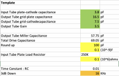
Get out your copy of the RCA tube manual that contains the interelectrode capacities of the tubes to be used. In this case we are calculating the 3db down frequency of the interstage network between the 6C6 & the 2A3.
So for the 2A3 the grid-plate capacity is 16.5 pF. The 2A3 input capacity is 7.5 pF. And the output capacity of the 6C6G is 6.5 pF.
To account for Miller Effect of the 2A3, we need to know the 2A3 gain. For a triode power stage, gain depends on the load resistance but for this calc by eyeball I just used G = 3.5. The Miller Capacity is then 3.5 X 16.5 or 57.75 pF.
That all adds up to 71.75 pF, (57.75 + 7.5 + 6.5)pF. Making allowances for strays of wiring capacity conveniently rounds out to ~100 pF. Or 0.1(10^-9) F. All must be driven by the 6C6 load resister of 250K or 0.25( 10^6) Ohms. The Time constant RC is the product of those two numbers, 0.025 seconds. Be careful how you collect the exponents of those numbers. Otherwise crazy results follow.
Stuffing that into the formula for RC frequency 3 db down looks like ~0.16 / RC. The freq response of the circuit is already down 3 db at 6.4 KHz simply thru the interstage coupling. There are still other factors such as the response of the OPT & the input circuit. Looks like the original input Pot has been changed to 100K. That is much better. The lowest drive impedance to the following grid is now 25K when the slider is at mid resistance. But there needs to be a decoupling cap at the input of something like 0.1 microF. 🙂
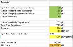
For the simple 6SL7-2A3, the calculated HF roloff at 3dB down is 16KHz. For 5842, it's 267KHz (screenshots attached). At least, I think I did the 5842 correctly: its P-K capacitance is 1.8pF and I had a 6K plate load resistor on it.
How would we calculate this with the SRPP 6SL7, given that the signal to the output stage is taken from the union between the upper triode cathode and lower triode plate? Does the cathode resistance of the upper triode become the plate load resistor for the lower triode? Does the grid-cathode capacitance of the upper triode become the output capacitance in the calculation?
NB: I forgot to change the stated load resistor value in the screenshots. 6SL7 was 100K and 5842 was 6K.
Attachments
Another Shortcut (Really??)
Many would agree that calculating paralleled resistances is a misery. So why do we do that, when the problem could more easily be solved by adding conductances. In this particular example we could take the resistances to be 0.25 M, 0.5 M & 1 M. As conductances these become in order 4 micromhos, 2 micromhos & 1 micromho. The total conductance is then 7 micromhos. And the resistance is 1/7th M or ~141K. Done. Without use of a Rechner (Calculator).
Three & four figure accuracy is hardly needed, the active devices we are using vary from lot to lot and quite a bit even as they pass a signal. So for this amplifier the interstage RC time constant becomes 0.147 (10^6) x 0.1 (10^-9) or 0.0147 milliSeconds. And f2 the 3 db down HF freq is ~10.88 KHz.
Could we have taken yet another shortcut? Sure, in this case we already knew the unwashed freq to be 6.4 KHz. And the ratio of the rough resistance to the more accurate calculation is 250:147 or about 5:3. So 5/3rds times 6.4 KHz is 10.67 KHz, close enough.
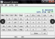
Adding conductances is real easy on a pocket calculator running RPN (Reverse Polish Notation). Simply enter the resistance & press the 1/x key. Then enter another resistance & press the 1/x key again. Then press add, followed by 1/x, all done.
RPN, no brackets to get lost in, solves math problems from the inside to the final result just as we do with pencil & paper. And see the intermediate results as we move thru the problem. I’m still using an original HP67. With a red LED display, far better than what is in an HP35s I have. Almost impossible to use because the display is so poor.
A free download of the Fairwood Calculator that runs in RPN is at https://sourceforge.net/projects/fwcalc/
There is an error in my previous post, the RC time constant should read 0.025 milliSeconds.
Many would agree that calculating paralleled resistances is a misery. So why do we do that, when the problem could more easily be solved by adding conductances. In this particular example we could take the resistances to be 0.25 M, 0.5 M & 1 M. As conductances these become in order 4 micromhos, 2 micromhos & 1 micromho. The total conductance is then 7 micromhos. And the resistance is 1/7th M or ~141K. Done. Without use of a Rechner (Calculator).
Three & four figure accuracy is hardly needed, the active devices we are using vary from lot to lot and quite a bit even as they pass a signal. So for this amplifier the interstage RC time constant becomes 0.147 (10^6) x 0.1 (10^-9) or 0.0147 milliSeconds. And f2 the 3 db down HF freq is ~10.88 KHz.
Could we have taken yet another shortcut? Sure, in this case we already knew the unwashed freq to be 6.4 KHz. And the ratio of the rough resistance to the more accurate calculation is 250:147 or about 5:3. So 5/3rds times 6.4 KHz is 10.67 KHz, close enough.
Adding conductances is real easy on a pocket calculator running RPN (Reverse Polish Notation). Simply enter the resistance & press the 1/x key. Then enter another resistance & press the 1/x key again. Then press add, followed by 1/x, all done.
RPN, no brackets to get lost in, solves math problems from the inside to the final result just as we do with pencil & paper. And see the intermediate results as we move thru the problem. I’m still using an original HP67. With a red LED display, far better than what is in an HP35s I have. Almost impossible to use because the display is so poor.
A free download of the Fairwood Calculator that runs in RPN is at https://sourceforge.net/projects/fwcalc/
There is an error in my previous post, the RC time constant should read 0.025 milliSeconds.
Attachments
jhstewart,
You wanted me to post some examples of amplifiers that I have designed and built.
So, I am asking you for your opinion (and other posters on this thread too).
Should I post the schematics on this thread, or should I start a new thread?
I will only do 1 or 2 posts at a time, and there could be a lot of time between posts.
Some designs are single ended, and some are push pull.
I would welcome (within reason) a few questions about my designs, for those who are curious about them.
So, what are everyones opinions? Should I:
Either put the variety of amplifiers in this thread,
Or start a new thread?
P.S. Thanks for the conductance lesson.
And . . . I am still using my HP 11 that I purchased in 1985 (retired my very nice Japanese Bamboo Post Versalog at that time).
I would say leave it up to the original poster to decide whether its better to post them here or on a separate thread.
My opinion, for what its worth, is that we need more threads like these - so start a new one ;-)
My opinion, for what its worth, is that we need more threads like these - so start a new one ;-)
Better in its own thread would be my vote. Lets see what others think. And the OP. 🙂You wanted me to post some examples of amplifiers that I have designed and built.
So, I am asking you for your opinion (and other posters on this thread too).
I've an Abacus direct from Malaysia where my brother lived for 30 yrs. But never did figure it out.And . . . I am still using my HP 11 that I purchased in 1985 (retired my very nice Japanese Bamboo Post Versalog at that time).
I think its math is based on numbers 2 & 5. I vaguely recall an early computer of US manufacture
that also use something based on 2 & 5. Think it was a Royal McBee?? Need to check that out someday..
The IBM gang printers before SS used relay logic to control the machine, it had mechanical counters
that used a scheme called 9s Compliment. Might still be in a museum someplace.
Yes indeed, and post as many designs as you like. Many here would like to see and discuss your work.My opinion, for what its worth, is that we need more threads like these - so start a new one ;-)

Hi Chris,Is there a typo with V2B's grid connection?
All good fortune,
Chris
no, it is right
jdrouin
Regarding the 6C6 version, you might like to try a change to the operating point of the 6C6, which worked for me many moons ago. The idea was from Thorsten Loesch, Joe Esmilla and Joe's Russian mate, forgot his name. Referring to my notes I made and your schematic, we have the same B+ from the power supply and the following changes.
1. Change anode resistor to 75k, resulting in 150V at the anode
2. Change cathode resistor to 1k, resulting in 2.4V at the cathode and increasing cathode current to 2.4mA
3. Increase the cathode bypass cap to 100uF
4. Change the screen resistor to 470k, resulting in 75V at the screen
5. Increase the screen bypass cap to 3uF
For the 2A3, you might change the coupling cap to 0.22uF and the grid resistor to 330k, also increase the cathode bypass cap to 100uF.
Suggest trying the 6C6 mods first, see if you like them, and if so do the 2A3 mods, usual one thing at a time mantra.
Yes, I did exactly that change last night, actually, and the calculated HF rolloff of -3dB is at about 22KHz. I haven't changed anything on the 2A3 yet: it's still running at 250Vak/60mA with the 470K grid leak. The input cap is actually 0.15uF PIO, which I neglected to put in the attachments above. Anyway, I definitely hear the change, with more "air" and high frequency response. I'm grateful to have learned how to consider HF rolloff because I've never come across that aspect of designing/building before.jdrouin
Regarding the 6C6 version, you might like to try a change to the operating point of the 6C6, which worked for me many moons ago. The idea was from Thorsten Loesch, Joe Esmilla and Joe's Russian mate, forgot his name. Referring to my notes I made and your schematic, we have the same B+ from the power supply and the following changes.
1. Change anode resistor to 75k, resulting in 150V at the anode
2. Change cathode resistor to 1k, resulting in 2.4V at the cathode and increasing cathode current to 2.4mA
3. Increase the cathode bypass cap to 100uF
4. Change the screen resistor to 470k, resulting in 75V at the screen
5. Increase the screen bypass cap to 3uF
For the 2A3, you might change the coupling cap to 0.22uF and the grid resistor to 330k, also increase the cathode bypass cap to 100uF.
Suggest trying the 6C6 mods first, see if you like them, and if so do the 2A3 mods, usual one thing at a time mantra.
These kinds of discussions are really helpful to people who come to this hobby without a science or engineering background, like me. Without any disciplinary context, I don't know what I don't know. But now I know. 🤔
Re: taking the broader discussion to another thread: it's up to you all. While my interest at the moment is more pragmatically focused on the operating specifics of these circuits and learning how to calculate various aspects like HF rolloff, to incorporate into design, I certainly don't mind broader conversations happening around that. It can be interesting to see what portals and tangents emerge from the concrete, specific work we do. Let it rip!
Jeff
I've really enjoyed this thread. Don't have much technical to contribute. But based on your last post, wanted to offer the following:
My first amplifier build was the JE Labs SE 2A3 "Deluxe." It's a three stage integrated amplifier, with the first stage DC coupled to the second, and the second RC coupled to the output.
I thought it sounded great... Until I built a two stage 45 amp based on Ale Bartola's work and using two of his "gyrator" boards for the input plate load. A/B comparing the two amplifiers, I discovered that the JE Labs 2A3 Deluxe had a thick, almost syrupy character compared to the 45.
This could be due to the 2A3 being loaded at 3.5k and the 45 being loaded at 5k. I'm actually going to do a shootout of two new 5k output transformers for the 2A3 amp soon, so we'll find out. But it also had to do with the three stage design which no doubt introduced a lot of extra distortion. JE seems to prefer the older circuits/approaches and, at least historically, has listened to his systems using speakers which are not necessarily capable of output above 15kHz. Just a caveat about potential "house sound" there.
TL;DR I think you're taking the right approach of building circuits from multiple sources. You will avoid mistakes/arbitrary predilections that way. Looking at the designs you've used so far, the only thing I would add is that you should also consider a design which uses a plate choke or an active load, like a CCS. It's quite different from RC coupling.
Keep on tinkering!
I've really enjoyed this thread. Don't have much technical to contribute. But based on your last post, wanted to offer the following:
My first amplifier build was the JE Labs SE 2A3 "Deluxe." It's a three stage integrated amplifier, with the first stage DC coupled to the second, and the second RC coupled to the output.
I thought it sounded great... Until I built a two stage 45 amp based on Ale Bartola's work and using two of his "gyrator" boards for the input plate load. A/B comparing the two amplifiers, I discovered that the JE Labs 2A3 Deluxe had a thick, almost syrupy character compared to the 45.
This could be due to the 2A3 being loaded at 3.5k and the 45 being loaded at 5k. I'm actually going to do a shootout of two new 5k output transformers for the 2A3 amp soon, so we'll find out. But it also had to do with the three stage design which no doubt introduced a lot of extra distortion. JE seems to prefer the older circuits/approaches and, at least historically, has listened to his systems using speakers which are not necessarily capable of output above 15kHz. Just a caveat about potential "house sound" there.
TL;DR I think you're taking the right approach of building circuits from multiple sources. You will avoid mistakes/arbitrary predilections that way. Looking at the designs you've used so far, the only thing I would add is that you should also consider a design which uses a plate choke or an active load, like a CCS. It's quite different from RC coupling.
Keep on tinkering!
Part of the problem with the JE Labs circuit is that the driver stage doesn't have enough current or voltage swing to effectively drive a 2A3 or 300B. It's really just the first two stages of a classic Williamson, which was designed as a voltage amp/phase splitter to drive the next stage, which was a differential 6SN7 to drive the output tubes. It was never designed to drive a power triode, and so it really falls short of what you need. It's "pleasant" but it doesn't really do the job.
Good to see that you compared them. The endless variations on the same 6SN7 type driver all have the same gloopy sound that you found. The driver is too feeble (as noted) and the unnecessary extra stage adds increased-order distortion terms, & vagueness.My first amplifier build was the JE Labs SE 2A3 "Deluxe." It's a three stage integrated amplifier, with the first stage DC coupled to the second, and the second RC coupled to the output.
I thought it sounded great... Until I built a two stage 45 amp based on Ale Bartola's work and using two of his "gyrator" boards for the input plate load. A/B comparing the two amplifiers, I discovered that the JE Labs 2A3 Deluxe had a thick, almost syrupy character compared to the 45.
There are many better ways of driving 2A3s and 300Bs to sound much better than 6SN7s; and now that the 6SN7 is considered a vintage rarity, it's also possible to save a lot of cash. A straightforward pentode stage with JJ EL84s or TV IF pentodes is a great place to start for anyone wishing to avoid getting stuck in 6SN7 syrup.
2A3 SET is a bad idea. Because of its limited output, it has to be used close to full power, which means unacceptable high level of distortion. Although 2H distortion is musically benign, it is associated with high levels of IMD. IMD may be acceptable with simple "girl and guitar" kinds of music, but not with complex music.
Because of limited power, such an amplifier has virtually no headroom for dynamic peaks occurring in many kinds of music.
Such an amplifier requires speaker's with sensitivity in excess of 100 dB, which means horns. Horns introduce coloration and reflections, their waterfall is horrible. No possibility of using the best available high frequency drivers.
I believe SET should use at least 300B, or better big tubes such as 845 or GM70.
Last edited:
Whis I had read this years ago.2A3 SET is a bad idea. Because of its limited output, it has to be used close to full power, which means unacceptable high level of distortion. Although 2H distortion is musically benign, it is associated with high levels of IMD. IMD may be acceptable with simple "girl and guitar" kinds of music, but not with complex music.
Because of limited power, such an amplifier has virtually no headroom for dynamic peaks occurring in many kinds of music.
Such an amplifier requires speaker's with sensitivity in excess of 100 dB, which means horns. Horns introduce coloration and reflections, their waterfall is horrible. No possibility of using the best available high frequency drivers.
I believe SET should use at least 300B, or better big tubes such as 845 or GM70.
I'd have a really nice system, instead of the really awesome one I have now.
2A3 SET is a bad idea. Such an amplifier requires speaker's with sensitivity in excess of 100 dB, which means horns. Horns introduce coloration and reflections, their waterfall is horrible. No possibility of using the best available high frequency drivers.
I believe SET should use at least 300B, or better big tubes such as 845 or GM70.
All this may be true of large rooms and higher volume levels. I'm not going to argue that because I don't live in a huge room or play head-banging music.
But it isn't true of smaller rooms and moderate sound levels. And for those who listen in smaller rooms at moderate levels it sets in stone some unhelpful "advice" regarding things like speakers.
My bookshelf speakers are around 88db efficient. And the amp works with 2 stages, the first being a 6J5 variety, the CV6. I've never seen any advice anywhere that suggests that this is even remotely possible, but believe me it works perfectly well.
I started with 300b because I bought into all the advice that this was the output valve to use. When I substituted a 2a3 I knew immediately that this was a better sounding valve, and I haven't gone back to the 300b.
So depending on your room size and sound levels I would suggest that you try a 2a3 SET for yourself and make up your own mind. You may not need either horns or pentodes and you can optimise your system around what sounds best to your ears.
Power isn't everything. I find that the 2A3 handles complex program matter better than the 300B, probably due to the superior damping factor from its 800R plate. And that's an A-to-A comparison using the same WE91A circuit topology and input tube. On a very efficient single fullrange driver, as I'm using, it sounds exquisite, though of course that's a matter of taste. An SE amp with single fullrange driver won't do justice to a symphony orchestra in full flight (that's not why we build them, anyway), but it gets damned close with a good 2-way speaker like Altec Valencia.2A3 SET is a bad idea. Because of its limited output, it has to be used close to full power, which means unacceptable high level of distortion. Although 2H distortion is musically benign, it is associated with high levels of IMD. IMD may be acceptable with simple "girl and guitar" kinds of music, but not with complex music.
Because of limited power, such an amplifier has virtually no headroom for dynamic peaks occurring in many kinds of music.
Such an amplifier requires speaker's with sensitivity in excess of 100 dB, which means horns. Horns introduce coloration and reflections, their waterfall is horrible. No possibility of using the best available high frequency drivers.
I believe SET should use at least 300B, or better big tubes such as 845 or GM70.
Speaking of WE91A topology, here's a pic showing the JE Labs edition of the Radiotron SE 2A3 I've been listening to on the breadboard for a few days. I updated in red where my measurements or specs differed from Joseph's schematic. Main differences are that I used a 750R cathode resistor instead of 880R, mainly because that part of the breadboard has so many intimately arranged components that I didn't have the energy to undo and then redo it all, and I kept the 0.1uF supply grid bypass cap instead of 2.8uF (I didn't have any caps around that value, so I didn't bother).
This circuit sounds very similar the WE91A 300B circuit I'd been running on the breadboard for about 3 years, which is not surprising given that it essentially replicates the topology at 2A3 voltage levels but without the feedback loops. It has noticeably improved high frequency response over the original Radiotron schemo, which jhstewart calculated to roll off -3dB at around 6.5KHz. I calculated this version to roll off -3dB at around 22KHz. It reproduces the timbre of acoustic instruments beautifully, with loads of sustain and "air." It sounds fast, dynamic, and detailed but not edgy. It has what I would describe as a "glassy" sonic signature. Overall a very musical amp. I still think the 6SL7 amps are even better, especially the simple version (more vibrant, more everything), but I'll listen again because who knows what my acoustic memory is doing with all this.
Next stop will be the Lipman/Garber direct-coupled 6SF5-2A3.
Last edited:
I listen to my 2A3 (also currently using 6J5 drivers) on 92dB Polk Audio Monitor Series 2 from the early 90s. In my ~18x14 ft living room, it sounds great.All this may be true of large rooms and higher volume levels. I'm not going to argue that because I don't live in a huge room or play head-banging music.
But it isn't true of smaller rooms and moderate sound levels. And for those who listen in smaller rooms at moderate levels it sets in stone some unhelpful "advice" regarding things like speakers.
My bookshelf speakers are around 88db efficient. And the amp works with 2 stages, the first being a 6J5 variety, the CV6. I've never seen any advice anywhere that suggests that this is even remotely possible, but believe me it works perfectly well.
I started with 300b because I bought into all the advice that this was the output valve to use. When I substituted a 2a3 I knew immediately that this was a better sounding valve, and I haven't gone back to the 300b.
So depending on your room size and sound levels I would suggest that you try a 2a3 SET for yourself and make up your own mind. You may not need either horns or pentodes and you can optimise your system around what sounds best to your ears.
That said, I do appreciate the idea that more power does introduce qualitatively different listening experiences. Even the step up from a 45 to a 2A3 (with very similar circuits) is more than just the same music, but louder. The bass and dynamics are better.
- Home
- Amplifiers
- Tubes / Valves
- Developing a 2A3 SET