A123 batteries are quite expensive in my country so I intend to use some 'no name' lifepo4 batteries that I already have until I can buy new A123's.
My current batteries are a few years old so some may not be in great condition - l'm guessing the battery management system on the power supply will be able to cope with some of my batteries not being as good a shape as others in the PS?
My current batteries are a few years old so some may not be in great condition - l'm guessing the battery management system on the power supply will be able to cope with some of my batteries not being as good a shape as others in the PS?
Hi Ian,ultra capacitor power supply 1st prototype PCB order placed. You will see it soon.
Regards,
Ian
I see that the last information about ultra capacitor power supply was 3 months ago. Could you please share info about the progress of UCPS?
Thanks,
Bern
Maybe the group buy has kept him busy?
Yes very busy! I know from experience manufacturing all this for us lucky people is a right royal pain in the ... Please be patient and don't wear poor Ian out

The ultra capacitor supply and OPA861 I/V stages will come, Ian just has to clear the decks before he can get back on it.

Agree, Ian is ultra-busy with his current GB, with almost 200 listed subscribers (typically more join after it is started, but never add their info to the interest list, so likely more than 200 total!).
I too am VERY interested in his UC supply and will be watching closely for it to emerge.
In the meantime, I have received my LiFePO4 supply and spent the last 2 evenings assembling it. During this process, I became VERY aware of the safety hazards in dealing with 10 un-protected and partly charged LiFePO4 cells during the assembly... and even more so when you have them soldered onto the board and now not only have the cells' terminals as possible accidental short contact points, but now a number of component pads and leads on the board too.
I'll be posting the 'best practices' that I developed (in some cases the hard way) while doing this assembly. Do understand I have been building DIY'd audio gear of all sorts (speakers, electronics, turntables, tonearms, solid state and tube) since 1975, so I am not a beginner in this realm. AND in my model aircraft and helicopter hobby, I have been building battery packs of all sorts including Lithium-Polymer since 2006. AND I still found some ways to make mistakes.
IF you assemble your cells to your board either before I post my suggestions OR decide not to follow them, take extreme care. Each cell will put over 200A into a dead short, which will weld and/or vaporize metal. AND shorted cells can overheat with dire consequences.
Don't take this project lightly, before assembly, during, or after and during use!
Greg in Mississippi
I appreciate this warning and will heed your advice, and await the best practices suggestions (actually I am awaiting my parcel from Canada too!).
As a side note so that I might decide if I already have what I need, what size/width solder tip do you think is most appropriate?
@Simon Dart,
I have a prototype board of Ian's OPA861IV here ready to go. Hope to trial it this weekend.
Hopefully he sells it assembled, some of the parts were challenging for hand-assembly!
Greg
I have a prototype board of Ian's OPA861IV here ready to go. Hope to trial it this weekend.
Hopefully he sells it assembled, some of the parts were challenging for hand-assembly!
Greg
Don't take this project lightly, before assembly, during, or after and during use!
Greg in Mississippi
Thank you! Greg for the warning.
If you found it a challenge then everyone needs to pay attention. I have one on the way so I’m going to wait for your guidelines before going any further.
As always thanks for sharing.
Tips on assembling and using the LiFePO4 Power Supply safely part 1
As I suggested above, you need to take extreme care assembling and using the LiFePO4 supply. Why?
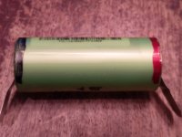
- The cells themselves are capable of sourcing a tremendous amount of current especially into a dead short. I bought my cells here:
A123 LiFePO4 26650 Rechargeable Cell: 3.3V 2500 mAh, 50A Rate, 8.25Wh, ANR26650M1B, ANR26650M1-B
I did this instead of going for used cells or ones of questionable origin just to make sure I was getting the best from this supply. NOTE the cells are RATED for 120A into a less than 10 second discharge. THEY ARE RATED FOR THIS!!! IF this is what they are rated for, imagine what they'll do into a dead short! OR if you just TOUCH them on the board in reverse polarity!
- When you are working with the raw cells, each cell only has 2 ends and a finite number of shorting paths. When you have them installed, you now have 10x the number of direct battery short paths... AND many pads and components on the board are now in direct connection with the cells, so they add even more shorting paths. An assembled board requires MUCH MORE care than a raw cell.
- If you are like me, you leave tools around on your workbench when working on a project. This is ok for most situations, but here they become possible short paths. You need to maintain a pristine work area while assembling or working on this to avoid inadvertent tool shorts.
- Most people have little experience working with live low voltage high current sources like this. I do. AND even with that experience AND taking a lot of care, I made some inadvertent contacts. You need to be on your toes ALL THE TIME with this project.
Ok, having said that, here's my best practices...
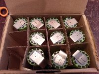
First, ensure your batteries are safe as soon as you receive them. Mine arrived in a carton with individual recesses for each cell (see pix). Yours should arrive with some means of insulating each cell from the others. Confirm that and make sure to maintain them in that state, only pulling them out one at a time as you use them.
AND ALWAYS wear safety glasses while working with these cells and this board!
Next, prepare to assemble by doing the following:
- Use a red and a black marker to mark the polarity of each cell so you have a clear visual while working with them (see pix).
- Use a good pair of side cutters to clip all of the component leads on the bottom of the board near where the batteries mount. Most of these are where the relays and terminals are installed into the board. These can be potential short points when installing, especially when trimming the tabs.
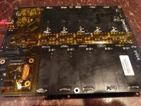
- Use good tape to cover these strip of components and leads on the bottom of the board between the 2 rows of cells (see pix). I used Kapton tape, other durable tapes will work as well. I also covered the bottom of the board where the controls are mounted. It's a good idea to do the same to the output underside, but I did not do that on mine.
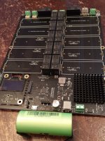
- Select a non-conductive work area and prepare it by clearing off an area about 2x size of board (see pix)
- Select a soldering iron and tool storage area outside of the cleared work area. ALWAYS return your tools and iron to that area when you put them down, don't leave them in the cleared work area. For tools you will need your soldering iron and good solder, side cutters to cut the tabs once soldered, and shields as below
- Test fit a single tab from a single cell into one of the outer edge of cell mounting slots to determine if you need to trim your tabs to fit. I had to remove about 1/16" (roughly 1.5mm) from one edge of each tab. I did this with a pair of tinsnips just before I assembled each cell onto the board. See more below.
- Select a high-watt soldering tool with a broad tip, the tabs and the soldering slots will soak up a lot of heat. I used my Weller WES51 soldering station and the medium-broad (about 3/32" or 2mm) tip. I also have a Weller SPG40 iron that would have worked as well. The WES51 worked well to solder the cells in place. It does not have sufficient heat capacity to remove a cell!
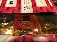
- Cut a couple pieces of heavy paper or light card stock that will fit the length of the board and are as wide as the area between the cell mounting slots. You want to use these to cover the board as you solder to make sure your solder does not short on anything. Also make up 4 multi-layer tape strips about 1/2" (12.5mm) and 2" (48mm long) to use as shields around each tab as you solder. I used Kapton for this, again other tapes will work, but Kapton is very good for this
- Ensure you have removed all distractions from the area before starting. Having a toddler pick up a tool and touch it to a cell or a board, a cat walk across your workspace, or something exciting happen on TV and you move your soldering tip while distracted could all be very bad things. If need be, move your workspace into an area where you are free from distraction.
End of part 1, to be continued...
Greg in Mississippi
As I suggested above, you need to take extreme care assembling and using the LiFePO4 supply. Why?
- The cells themselves are capable of sourcing a tremendous amount of current especially into a dead short. I bought my cells here:
A123 LiFePO4 26650 Rechargeable Cell: 3.3V 2500 mAh, 50A Rate, 8.25Wh, ANR26650M1B, ANR26650M1-B
I did this instead of going for used cells or ones of questionable origin just to make sure I was getting the best from this supply. NOTE the cells are RATED for 120A into a less than 10 second discharge. THEY ARE RATED FOR THIS!!! IF this is what they are rated for, imagine what they'll do into a dead short! OR if you just TOUCH them on the board in reverse polarity!
- When you are working with the raw cells, each cell only has 2 ends and a finite number of shorting paths. When you have them installed, you now have 10x the number of direct battery short paths... AND many pads and components on the board are now in direct connection with the cells, so they add even more shorting paths. An assembled board requires MUCH MORE care than a raw cell.
- If you are like me, you leave tools around on your workbench when working on a project. This is ok for most situations, but here they become possible short paths. You need to maintain a pristine work area while assembling or working on this to avoid inadvertent tool shorts.
- Most people have little experience working with live low voltage high current sources like this. I do. AND even with that experience AND taking a lot of care, I made some inadvertent contacts. You need to be on your toes ALL THE TIME with this project.
Ok, having said that, here's my best practices...
First, ensure your batteries are safe as soon as you receive them. Mine arrived in a carton with individual recesses for each cell (see pix). Yours should arrive with some means of insulating each cell from the others. Confirm that and make sure to maintain them in that state, only pulling them out one at a time as you use them.
AND ALWAYS wear safety glasses while working with these cells and this board!
Next, prepare to assemble by doing the following:
- Use a red and a black marker to mark the polarity of each cell so you have a clear visual while working with them (see pix).
- Use a good pair of side cutters to clip all of the component leads on the bottom of the board near where the batteries mount. Most of these are where the relays and terminals are installed into the board. These can be potential short points when installing, especially when trimming the tabs.
- Use good tape to cover these strip of components and leads on the bottom of the board between the 2 rows of cells (see pix). I used Kapton tape, other durable tapes will work as well. I also covered the bottom of the board where the controls are mounted. It's a good idea to do the same to the output underside, but I did not do that on mine.
- Select a non-conductive work area and prepare it by clearing off an area about 2x size of board (see pix)
- Select a soldering iron and tool storage area outside of the cleared work area. ALWAYS return your tools and iron to that area when you put them down, don't leave them in the cleared work area. For tools you will need your soldering iron and good solder, side cutters to cut the tabs once soldered, and shields as below
- Test fit a single tab from a single cell into one of the outer edge of cell mounting slots to determine if you need to trim your tabs to fit. I had to remove about 1/16" (roughly 1.5mm) from one edge of each tab. I did this with a pair of tinsnips just before I assembled each cell onto the board. See more below.
- Select a high-watt soldering tool with a broad tip, the tabs and the soldering slots will soak up a lot of heat. I used my Weller WES51 soldering station and the medium-broad (about 3/32" or 2mm) tip. I also have a Weller SPG40 iron that would have worked as well. The WES51 worked well to solder the cells in place. It does not have sufficient heat capacity to remove a cell!
- Cut a couple pieces of heavy paper or light card stock that will fit the length of the board and are as wide as the area between the cell mounting slots. You want to use these to cover the board as you solder to make sure your solder does not short on anything. Also make up 4 multi-layer tape strips about 1/2" (12.5mm) and 2" (48mm long) to use as shields around each tab as you solder. I used Kapton for this, again other tapes will work, but Kapton is very good for this
- Ensure you have removed all distractions from the area before starting. Having a toddler pick up a tool and touch it to a cell or a board, a cat walk across your workspace, or something exciting happen on TV and you move your soldering tip while distracted could all be very bad things. If need be, move your workspace into an area where you are free from distraction.
End of part 1, to be continued...
Greg in Mississippi
Attachments

Default Tips on assembling and using the LiFePO4 Power Supply safely part 2
Assemble Cells to board:
- First, keep focused on what you are doing. This is no time to check a text or email or watch TV. Stick with this, don't get distracted!
- With your board your cleared workspace, pull a cell out of your storage. Mine came with the tabs bent against the cell sides, straighten them.
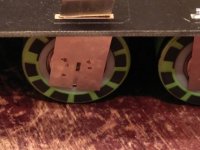
- IF you need to trim the tabs, bend them away from the cell ends to cut them to prevent the tinsnips from touching the cell end (see pix)... on the positive end of the cell, the edges are negative and you can short through the cell covering. Make sure to make your cut long enough that the full tab will go into the mounting slot and the cell will rest on the circuit board. Once you have the tabs cut, first straighten any bent edge or corner that could dig into through the cell covering and short. Then I suggest putting a small piece of Kapton or similar tape where the tab could rest against the cell end and short. I didn't do this, but I wish I had. Once you are done with all of this, straighten the tab back alongside the end.
- Again, test fit each tab one at a time into the outer tab slot to confirm they now fit. Re-trim if needed.
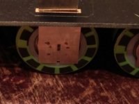
- VERY DELIBERATELY, hold the cell up and confirm you have it oriented with the correct polarity (see pix), positioning the positive side to the board centers where the relays are and the negative side to the outside. I inserted the positive tab into the center slot first, then carefully touched the negative tab to the mounting slot to ensure no spark before inserting it. THAT IS NOT TOO CAUTIOUS!
- After inserting both tabs, I set the board on a couple of tape rolls cell-side up and before soldering, adjusted the cell so it was square to the board (see pix). Then I soldered the outside (negative) tab from the top to hold it in.
- After that soldering, I flipped the board over, put the 4 pieces of multi-layer tape around the solder slot (see pix) and covered the rest of the board with the paper shields (see pix) before continuing soldering.
- When soldering, you want to bring your solder from the closest edge to the slot you are soldering and arc it high over the board so it cannot short on the board. Also keep your soldering tip angle high for the same reason. Doing both of these, finish soldering the outer (negative) tab from the bottom.
- Before moving to the center (positive) tab, reposition the paper shields to either side of the soldered tab so that they cover the adjacent tabs. Then use a good set of side cutters THAT YOU ARE OK TO RUIN to trim the outer (negative) tab. I found it best to nibble in a millimeter or so at a time. You may need to bend the tab back and forth to get it to fully break free. It will be rough AND sharp... beware. AND tough to cut, so these cutters may not be good for much else afterwards. DO NOT USE SCISSORS OR TINSNIPS THAT MUST BE POSITIONED PARALLEL TO THE BOARD THAT CAN SHORT.
- Now move your protective tape square over to the inner (positive) tab and reposition the paper shields.
- VERY CAREFULLY route your solder up over the board and bring it down to solder the inner (positive) tab, again keeping both the solder and soldering iron angled high to prevent touching any portion of the board.
- Use those doomed side cutters again to trim the inner (positive) tab.
- Look closely for and remove any metal strips or shards from cutting the tabs.
- Repeat to assemble the next cell until all are mounted.
End of part 2, to be continued (but not tonight!)...
Greg in Mississippi
Assemble Cells to board:
- First, keep focused on what you are doing. This is no time to check a text or email or watch TV. Stick with this, don't get distracted!
- With your board your cleared workspace, pull a cell out of your storage. Mine came with the tabs bent against the cell sides, straighten them.
- IF you need to trim the tabs, bend them away from the cell ends to cut them to prevent the tinsnips from touching the cell end (see pix)... on the positive end of the cell, the edges are negative and you can short through the cell covering. Make sure to make your cut long enough that the full tab will go into the mounting slot and the cell will rest on the circuit board. Once you have the tabs cut, first straighten any bent edge or corner that could dig into through the cell covering and short. Then I suggest putting a small piece of Kapton or similar tape where the tab could rest against the cell end and short. I didn't do this, but I wish I had. Once you are done with all of this, straighten the tab back alongside the end.
- Again, test fit each tab one at a time into the outer tab slot to confirm they now fit. Re-trim if needed.
- VERY DELIBERATELY, hold the cell up and confirm you have it oriented with the correct polarity (see pix), positioning the positive side to the board centers where the relays are and the negative side to the outside. I inserted the positive tab into the center slot first, then carefully touched the negative tab to the mounting slot to ensure no spark before inserting it. THAT IS NOT TOO CAUTIOUS!
- After inserting both tabs, I set the board on a couple of tape rolls cell-side up and before soldering, adjusted the cell so it was square to the board (see pix). Then I soldered the outside (negative) tab from the top to hold it in.
- After that soldering, I flipped the board over, put the 4 pieces of multi-layer tape around the solder slot (see pix) and covered the rest of the board with the paper shields (see pix) before continuing soldering.
- When soldering, you want to bring your solder from the closest edge to the slot you are soldering and arc it high over the board so it cannot short on the board. Also keep your soldering tip angle high for the same reason. Doing both of these, finish soldering the outer (negative) tab from the bottom.
- Before moving to the center (positive) tab, reposition the paper shields to either side of the soldered tab so that they cover the adjacent tabs. Then use a good set of side cutters THAT YOU ARE OK TO RUIN to trim the outer (negative) tab. I found it best to nibble in a millimeter or so at a time. You may need to bend the tab back and forth to get it to fully break free. It will be rough AND sharp... beware. AND tough to cut, so these cutters may not be good for much else afterwards. DO NOT USE SCISSORS OR TINSNIPS THAT MUST BE POSITIONED PARALLEL TO THE BOARD THAT CAN SHORT.
- Now move your protective tape square over to the inner (positive) tab and reposition the paper shields.
- VERY CAREFULLY route your solder up over the board and bring it down to solder the inner (positive) tab, again keeping both the solder and soldering iron angled high to prevent touching any portion of the board.
- Use those doomed side cutters again to trim the inner (positive) tab.
- Look closely for and remove any metal strips or shards from cutting the tabs.
- Repeat to assemble the next cell until all are mounted.
End of part 2, to be continued (but not tonight!)...
Greg in Mississippi
Attachments
-
 9 Tab Soldering-Cutting protection 2 small.jpg490 KB · Views: 358
 -
 8 Tab Soldering-Cutting protection 1 small.jpg476.9 KB · Views: 754
 -
 7 Cell Alignment Right small.jpg205.8 KB · Views: 755
 -
 6 Cell Alignment Wrong small.jpg213.4 KB · Views: 766
 -
 5 Color Code to board small.jpg479.8 KB · Views: 750
 -
 2 Color-coding cells small.jpg383.7 KB · Views: 770
@Greg Stewart
Hi Greg,
You did great job. Thank you so much for sharing the very helpful and very professional experiences with the community.
Safety is always the first priority, especially for those high energy density components such as LifePO4 cells. A lot of people will benefit from you post. Appreciate!
Regards,
Ian
Thanks Ian. 1 more installment coming, likely this weekend.
I plan to clean this up and put in as an appendix to the manual.
Everyone else, if you see mistakes, things I missed, things needing clarification, please speak up.
Thanks!
Greg in Mississippi
P.S. For those in the US and Canada, I have had success charging the LiFePO4 supply with this unit from Jameco:
MKD66123400: Arndt : 40.8W AC-to-DC Unregulated Linear Table-Top Power Supply 12V 3.4A : Power Supplies & Wall Adapters
It is being discontinued and on close-out, with only 272 units left. So get them while you can. EDIT, only 267 left, at that price, I had to get a few for stock!
It is a tiny bit light on rated current, but has had no issues so far with my supply. AND for the price, it is hard to beat!
You will want to cut the included connector off to install your preferred connector solution. NOTE that on the unit that I used, the wire color codes were backwards... red was negative, green was positive. Open up the case, look at the small circuit board, and use your meter to test before installing your connector!
Last edited:
@Greg Stewart
Thank you! I needed these warnings and instructions! I most certainly would have distroyed the board/cells/my eyes.. Hope to receive my order next week, will be following your instructions step by step with a extra dose of careness 🙂
Thank you! I needed these warnings and instructions! I most certainly would have distroyed the board/cells/my eyes.. Hope to receive my order next week, will be following your instructions step by step with a extra dose of careness 🙂
@alazira,
Given that the recommended supply for one board is a minimum of 12V/3.5A, that should work ok.
BUT do remember that the non-isolated 5V/2A regulated DC output has a common ground with the 12V-19V input. SO while you could use that output from one of the boards, if you use that output from the other board, you must take care to avoid ground loops or shorting.
Greg in Mississippi

Greg
Many thanks for your guidance notes, I am duly cautioned. Well, frightened actually! What gloves would you recommend wearing whilst carrying out these procedures?
Many thanks for your guidance notes, I am duly cautioned. Well, frightened actually! What gloves would you recommend wearing whilst carrying out these procedures?
Greg
Many thanks for your guidance notes, I am duly cautioned. Well, frightened actually! What gloves would you recommend wearing whilst carrying out these procedures?
Hi Studley,
Although they're high current cells, there's not enough voltage to get shocked/electrocuted from these cells. You would need to put many in series to get shocked. That said, Greg's safety warnings are real, better take all possible precautions.
Do
- Home
- Amplifiers
- Power Supplies
- Develop ultra capacitor power supply and LiFePO4 battery power supply