You are welcome Nordic.
Post your picture for us...also your personal name please.
regards,
Carlos
Post your picture for us...also your personal name please.
regards,
Carlos

Morning uncle Charlie, trying to make me shy?
My name is Nico (pronounced as Knee-coo - like coo in cool) , but even my friends offline started calling me Nord or Nordic a long time ago, but yes, I am shy so thats it for now.
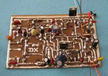
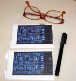
Here is progress on the etched board....
Appart from the PSU caps I guess you only need the rectifiers to go before this... I have big 25A case mount rectifiers I could use....
Its clear I got too used to regulated supplies... I feel totaly nekid looking at the bare supply arrangemebt for this amp...
What would you suggest, or is there some parts I missed?
My name is Nico (pronounced as Knee-coo - like coo in cool) , but even my friends offline started calling me Nord or Nordic a long time ago, but yes, I am shy so thats it for now.
Here is progress on the etched board....
Appart from the PSU caps I guess you only need the rectifiers to go before this... I have big 25A case mount rectifiers I could use....
Its clear I got too used to regulated supplies... I feel totaly nekid looking at the bare supply arrangemebt for this amp...
What would you suggest, or is there some parts I missed?
Attachments

All rigth Nico, you are shy...but you made image from you years ago...camera was not
so good those early days...you already presented yourself for us...if am not wrong...i think so.
No problems related that.
Nico...we spell the same in portuguese Knee co...short length in that "o"....strongest pronunciation in "ni"
Short form of Nicolau in Brazil.
.....................................................................................................
Dear nephew
This board, produced by RAJ, was not tested...at least Raj did not came to me to tell me nothing about his construction.
This makes this board untested.... it is possible that you may face some error......maybe not.
The supply schematic is beeing provided because i did not understood your needs related that stuff.
regards,
Carlos
Attachments
I hope i could face your needs
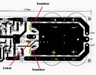
Snubbers are connected from positive line voltage to ground...also from negative line to ground.
It is made with a small ohms resistance in series with a capacitor...normally high voltage capacitor and this needs some calculation.
Well...i have not perceive sonics on this...but....not disturbing...may be good.
In the center you have the Zobel filter.... very alike the snubbers.
I hope i am helping you someway.
Fuse is small as you will have smaller power... you will use 25 volts DC symetrical.
regards,
Carlos
Attachments
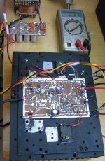
Ok Uncle Charlie, I will put it into eagle so we can confirm everything is consistant with the schematic.
Is there a specific schematic that you would consider the latest?
I think the one I used is correct, as it meshes with the actual pcb as far as I followed it...
My speakers are rated 8ohm 70W - 140W peak
My chipamp on +- 36V rails can't drive them to distortion... 🙂
What transformer would you choose with this in mind?
Related supply voltages and power output there's no magic
As output power will depends from the supply voltage as you know.
Your chip amplifier, using 36 plus 36 volts will, for sure, produce more power than Dx amplifier using 25 plus 25 volts.... not a fair sittuation to compare them
But you can do it if you adjust them to 10 watts rms peaks and start some comparison this way...i am interested to know if your chip can beat Dx amplifier...hehe
I know you are limiting your power to reduce costs and to substitute some transistors with others ones that will result cheaper for you.
Supply for a stereo Dx amplifier will need 400 watts of power (35 volts supplies)...this means that you will have DC voltage bigger than 31.8 volts with both amplifiers working at full powr over 4 ohms loads
Your amplifier, using 25 volts, will need a sligthly bigger than 200 watts supply, that will loose 10 percent it's voltage when when hard driven...voltage will fall to 22.5 under steady tone, full power, over 4 ohms loads...loosing more than that...seems the supply is not 200 watts..
We can "imagine" the transformer power only watching it..but this is not precise....if normal E type transformer...the area of the center leg will show you how much power it will hold...but you will have to dismount to obtain, exactly, this center leg sizes to calculate...not a very good idea.
The best way, is to install resistances draining that power at the DC output terminals.
I am having problems to understand you...my English is not good...please, explain your needs with more details to me.
regards,
Carlos
My transformer is 2x26VAC But it will only do 250va per rail if I understand correctly... which gives 35 - 36V DC depending on load...
Are you talking about AC or DC voltages?
Do I need 200W supply per channel?
What AC voltage transformer would you pick? forget about useing smaller sinks, I will try to get proper ones... this will allow experimentation with other class A topologies in future...
I am not trying to make cheap version, quite the opposite in fact, when considering the costs of sinks and transformers, the actual components cost seems small compared to anything else I did up to now...
This is my first GROWNUP AMP... and I will drive yo crazy before I flip the switch still.
If I can buy all parts for a project for R40, but do the same thing with nice caps it would cost say R80... but when the project costs R1000, then R40 doesn't matter anymore...
Transistor choice looks like
Q, Q2 BC640
Q3 BD139
Q5, Q5 MJE340/350
Q6 and Q7 depends on if I can get 2sa1943
A 320 watts transformer...or a little bit bigger will be enougth.
This means that you will have to install 15 ohms - 30 watts resistance into each rail and measure more than 32 volts under this condition.
Under loaded conditions, not to have more than 10 percent of DC voltage will be the best sittuation...but....many times, those losses goes around 30 percent...this means voltage will go to 29 Volts under load.... those numbers are not precise...around those numbers.
Not the best sittuation...but acceptable...power will reduce a little because of that, of course.
100 watts power over 4 ohms and 50 watts power over 8 ohms depends that your supply keep those 36 volts stable...real world is not that way....voltage losses happens...reason why people prefer to use a little bigger transformers...bigger voltage without load, as losses will happens...so...42 volts DC supplies may work better to provide 36 or 37 under hard driven conditions...or..stabilized supplies.
Loading your supply with resistances..you will measure what is really happening with them, and you will be 100 percent sure what is the power it will provide you....if enougth or not.
Of course you can do it with your amplifier...inserting music sources and working it till distortion starts...them measure this current...if hard, install sinusoidal generator into the input.... when the clipping starts, sonics of the signal will change enormously and you will perceive when clipping...even without scope this is easy to perceive..sounds turns strange immediatelly.
This is what you can do to discover your DC supply power...if enougth or not..... factory informations of course will be interesting (they lye!).... and "eye calculations" may help too.
Just produce a picture with a rule to provide size to me... and maybe i will tell you the transformer power...if standard "E" core transformers.
Using 35 volts supplies... stable voltage...virtual supply
2,3 plus 2,3 amperes will be drained from the supply during audition into clipping....with steady tone the measurement turns easier...and over 4 ohms loads
The consumption will be around 150 watts each channel and output power will be 100 watts each channel...needing a 320 watts supply.
Parts are the same of the last schematic published...of course you can reduce the input capacitor because it is big in size and really big for the need.... also you can reduce your rail condensers value..... R10, the gain control resistance must be keep around the schematic value...2K2 and you will need to adjust your bias.
There's a trick....install protective resistances in your rails...or lamps in series with your supply AC input....adjust off set measuring over a 8 ohms or 4 ohms resistive load (do not use speaker now!).... then go to bias.... adjust it to 50 to 100 miliamps..your choice, as you will need to check the VBE into the drivers and the output to see if match your needs)....now return to off set, as it is wrong again...re-adjust it once more....and return to bias to check it once more...now measure AC over the speaker or load terminals to observe if you have oscilations...not AC can be measured there with the input terminal shorted to ground...then put it to sound loud....go checking...monitoring the heatsink temperature.
Two output heatsinks...insulated if installed into metal chassis will be a better choice...as thermal transference will be better without insulators....mounting transistors directly over heatsink will be excelent!....
Also sand your transistor back side...that pretty chromium may disappear...transistor are not flat...use sandpapper, waterproof, number 500...grain 500....over a glass (flat surface) sand it till you observe that the surface turns flat (watching is very easy to understand that)
Be happy...feel the softness...the clear trebles... the excelent sound stage...the nice bass.... the good dinamics...the low noise and fidelity....and enjoy...i will be happy with you....and i will be dancing too.
To the ones that do not believe in simple schematics...a message for you folks in this attachment...click on it....tray to save..they may move.
regards,
Carlos
Attachments

Hey Uncle C, will answer some of the stuff you mentioned shortly after investigating...
I think my transformer will be too small... its about 140mm in all dimensions. I had it made, I was still a bigger noob, and just asked for 2 x 26VAC 5A .... which is why I think each secondary can only do 2.5A... not tested... It could be they made it 2 x 5A secondaries... they did mark it 250va... 26 x 5= 130, 130 x 2 =260
It is bigger than any transformer I saw in a amp yet... but I don't know how this size relates to power...
ow many watts 15R resistor do I need? I need a high wattage 20R resistor for a class-a headphone amp, any way to use that to save a few cents....?
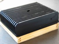
I think once we know which transformer will be powering my amp - which must be as good (almost same) as yours, we will know which heatsink etc., when looking at ambient temp etc... which is normaly 18-23C and low 30s in summer, benifit of living at the beach - moderate seasonal changes.... amp must run 14hours every day.
Yep I do the sanding thing.. the process is called lapping, like lapping soup up with your tongue... use water paper glued to a mirror... old trick I learned with overclocking computers... and dealing with general PC heat on hot summer days... 40C.
And use arctic silver no5 as thermal compound in stead of pads..
Thermal Conductance:
>350,000W/m2 °C (0.001 inch layer)
Thermal Resistance:
<0.0045°C-in2/Watt (0.001 inch layer)
I think my transformer will be too small... its about 140mm in all dimensions. I had it made, I was still a bigger noob, and just asked for 2 x 26VAC 5A .... which is why I think each secondary can only do 2.5A... not tested... It could be they made it 2 x 5A secondaries... they did mark it 250va... 26 x 5= 130, 130 x 2 =260
It is bigger than any transformer I saw in a amp yet... but I don't know how this size relates to power...
ow many watts 15R resistor do I need? I need a high wattage 20R resistor for a class-a headphone amp, any way to use that to save a few cents....?
I think once we know which transformer will be powering my amp - which must be as good (almost same) as yours, we will know which heatsink etc., when looking at ambient temp etc... which is normaly 18-23C and low 30s in summer, benifit of living at the beach - moderate seasonal changes.... amp must run 14hours every day.
Yep I do the sanding thing.. the process is called lapping, like lapping soup up with your tongue... use water paper glued to a mirror... old trick I learned with overclocking computers... and dealing with general PC heat on hot summer days... 40C.
And use arctic silver no5 as thermal compound in stead of pads..
Thermal Conductance:
>350,000W/m2 °C (0.001 inch layer)
Thermal Resistance:
<0.0045°C-in2/Watt (0.001 inch layer)
I will be over your sholder all time long if needed..just call me
using forum...of if you feel yourself shy if some problems happens, go directly to my mail.
You are welcome.
nanabrother@yahoo.com
I was talking about DC..... good condensers, or bad condensers... expensive condensers or junk condensers...all them will sound nice with this amplifier.
A very good will amplifier.....will not create you problems.... the only need is to avoid shorts, connection errors...inverted leads transistors (those BC639 are easy to make mistakes)...inverted power leads may destroy everything...well.... having care with it...using protective rail resistors...i can give you million percent guarantee that will work fine.
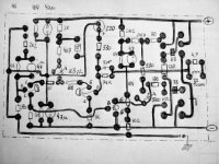
Of course, i cannot guarantee under hard errors..so... check it twice or three times...measure resistances from positive to ground and negative to ground...check all condenser polarities, as those standard boards, shown as transparences may create problems of invertion with misunderstanding it when observing the polarity....when watching over the board...watching the parts side....up will be positive...and down will be negative.
Resistance may be big...more than 30K....and invert your measurements probes.... logical results will appear from positive to ground compared to negative to ground.... remove rail condensers during measurement...and carefull not to do as i use to do...when re-installing condensers (board rail condensers) do not install them inverted as i use to make....hehe...they will explode with the gauge .22 long rifle sonics.
Always use protective glasses when first power on if you use to make mistakes (as i use to make)
I wish you luck!
regards,
Carlos
using forum...of if you feel yourself shy if some problems happens, go directly to my mail.
You are welcome.
nanabrother@yahoo.com
I was talking about DC..... good condensers, or bad condensers... expensive condensers or junk condensers...all them will sound nice with this amplifier.
A very good will amplifier.....will not create you problems.... the only need is to avoid shorts, connection errors...inverted leads transistors (those BC639 are easy to make mistakes)...inverted power leads may destroy everything...well.... having care with it...using protective rail resistors...i can give you million percent guarantee that will work fine.
Of course, i cannot guarantee under hard errors..so... check it twice or three times...measure resistances from positive to ground and negative to ground...check all condenser polarities, as those standard boards, shown as transparences may create problems of invertion with misunderstanding it when observing the polarity....when watching over the board...watching the parts side....up will be positive...and down will be negative.
Resistance may be big...more than 30K....and invert your measurements probes.... logical results will appear from positive to ground compared to negative to ground.... remove rail condensers during measurement...and carefull not to do as i use to do...when re-installing condensers (board rail condensers) do not install them inverted as i use to make....hehe...they will explode with the gauge .22 long rifle sonics.
Always use protective glasses when first power on if you use to make mistakes (as i use to make)
I wish you luck!
regards,
Carlos
Attachments
Will be enougth for 8 ohms purposes...in the 4 ohms sittuation
normally the comercial transformers do the same....they loose enormous voltage when you drive the unit into 4 ohms.
You can compensate using good sized electrolitic condensers in the supply... 20 thousand each rail will maintain enougth voltage to face some interesting 100 watts peaks of power over 4 ohms....will not hold continuous power...with steady signal generator into it's input..but will hold nice peaks of power..more than 100W of peak power for sure.... each channel...over 4 ohms
This may let those 2SC5200 happy...as it will work in the limit using 4 ohms...so....having losses of voltage....parfait!
Those testing resistances will be used for a second only....just to check voltage readings....so....even hardly under powered to continuous use....for instantaneous use they may survive.
Nordic....as you intend to use better transistors related the standard schematic...higher speed units...better, for safety, to increase the feedback capacitor to 12 picofarads and to increase the miller one to 22 or 27 picofarads...to avoid oscilation..those high speed units are a little problematic.
Do not tell people...they do not believe that...no chance to them to believe..but installing more diodes in parallel over your rectifier ....sonics increase...unbeliavable?....yes!..it is unbeliavable...i also do not believe that...but check that if you can....i also think that this is absolutelly non sense...but....having chance..check it...hehe...surprise!!!!
Soon you will be dancing and sending me loud thanks...and this will make me very happy!
South Africans and brazilians are not really white.... we are yellow or brown.... so...my choice of image was because of that....sorry that you are too much white....Nordic folk...i have not the white version dancing..;..do they dance?...ahahhahaha!
regards,
Carlos
Attachments

- Status
- Not open for further replies.
- Home
- Amplifiers
- Solid State
- Destroyer x Amplifier...Dx amp...my amplifier