This was already made and posted long time ago in our own thread dear Nordic.
But...if you have problems to search it i can try to do for you another one or to search the old one already published.
No problems.
regards,
Uncle Charlie.
......................................................................................................
Thank you Graham.
Very old style...hehe... i like those things..well..i have learned something this way..i think it is easy when have some sketches....or scratches..do not know the correct name.
regards,
Carlos
This Dx Standard was into Greg Home Pages
The difference is to check, over the emitter resistances, if you have 1 to 3 milivolts....so...if the ouput is conducting.
The Dx amplifier had not those emitter resistances, reason why was not asked to check there.
The current will be the one needed to "force" the output to conduction..from 45 to 60 miliamps i imagine....if you want precise i can give you zero error current..but each circuit will have slightly differences...check the emitter resistances..will be better...more correct and better for low volume sonics.
regards,
Carlos
Attachments

The series protection resistance is your choice... depends the one you have
Off course there are good values...and they are around 10 ohms to our 35 volts supply...this means that a maximum of 3.5 amperes will go into the board if you have shorts there... resistance zero...
In this sittuation, all voltage will be over the 10 ohms resistance and into the amplifier board rails you will have almost nothing and heat into the point you have the short.
If the amplifier was adjusted to a very high current.... misadjustment or problems..let's say 1 ampere...than 10 volts will be over the rail resistances.... or a single one if you have some problem into the board.... this will keep 25 volts to the circuit and it will operate fine this way....so... the voltage losses when you have misadjustments are not so big when using small resistances as 10 ohms or smaller than that... the problem, as you already perceived is that your protected current will be big... 3.5 amperes each rail...hummm... a little bit hot.
Because of that, some clever folks use 100 ohms as protection resistances... and some of them use those resistances under fuse holder.... well...they are genius...very good idea...you place the fuse and the resistance of 100 ohms is bypassed.... great!
Others use a led with resistance in series...if the fuse burns..current will cross the 100 ohms resistance and will produce voltage that will drive the led on...nice too.
Divide your voltage reading by the protective resistance value.
For instance.... 0.6 V reading.... means 600 milivolts...divide by 10 ohms, means you have a current of 60 miliamps...and this is perfect!
Into the output emitter resistances the voltage will depend by the emitter resistive value you select and is using.
Lets imagine 0.22 ohms resistance...lets, imagine 13.2 milivolts reading....
So..divide the voltage, in amperes, by the resistance to obtain the current:
0.0132 divided by 0.22 = 0.06A...... perfect too.
regards,
Carlos
Attachments

Re: This was already made and posted long time ago in our own thread dear Nordic.
You were right about the first word Carlos") Sketches is right. Scratches is what You get when playing too much with the cat
Sketches is right. Scratches is what You get when playing too much with the cat 
Great explanations, everybody has a chance to understand that way
destroyer X said:
i think it is easy when have some sketches....or scratches..do not know the correct name.
Carlos
You were right about the first word Carlos
Sketches is right. Scratches is what You get when playing too much with the cat Great explanations, everybody has a chance to understand that way


Ahahahahah!... Jacco is funny
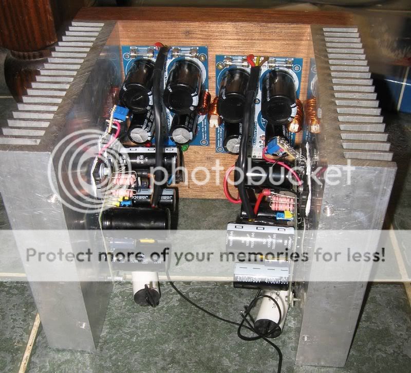
Hajame...beautifull construction... the most pretty Dx amplifier i could see constructed...your unit are really beautifull...could beat Greg Erskine construction, Ecat, Klaas and others that made a very nice job..well, this to my personal taste... i love those colours, the board colour, the small transformer, the panel... the small heatsinks..beautifull!
Also Nordic, congratulations dear nephew...very good work...now it is really pretty... the new photo machine is showing all the beauty for us.
I will post, now, VBEs to HRII..... Voltage referenced to ground and currents.
regards,
Carlos
I will attach 3 images having voltages and currents that will be good
to forum constructors, if need to debug, or to check if your amplifier is running alike the reference, this will be extremelly helpfull.... Voltages informed are referenced to ground, means that one of the voltimeter probe point will go to ground.
I want to say that i have made an error related the current adjustment of the output transistors for the HR II..... the measurement of voltage, over the emitter resistance (0.22 ohms) must be around 500 microvolts.
Around 2 miliamps will cross the emitter resistances, only to force the output to conduct.
The total positive rail current, must be equal or bigger than 30 miliamperes.
The total negative rail current, must be equal or bigger than 23 miliamperes
Here is the first attachment,
regards,
Carlos
Attachments


Those ones are informations of VBE
Volts from Base to Emitter... without signal.... load connected.
Those measurements differ from the simulator informations... i think the parameters into the simulator are different from my real transistors used.
I am posting the real measured voltages.
To the ones less experienced... VBE voltages are measured from base to emitter, one probe point goes to the base and the other goes to the emitter
Be carefull.... shorts from colector to base use to destroy the transistor.
regards,
Carlos
Attachments

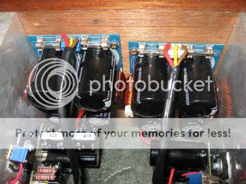
es44 said:Wow, that one looks really nice hajame.
Is Your case homemade, and do You have enough cooling just using the bottom. 10mm solid alu maybe ?
Thanks for you guys' appreciation!!
My case is not homemade. Just bought locally. It's made of 2mm aluminum only but for heat sinking it's enough. After playing loudly for 3 hours the case is just warm.
I choose this type of phenol paper board as it is said to have better insulation to prevent coupling. Oscillation had destroyed one of my tweeters
 so I have to prevent this as possible.
Those toroidals are ordered from farxxll. Their sizes are smaller than many brands for the same power rating. Mine are 300VA each.
Regards
hajame
Very nice amplifier you made.... pretty...very pretty one Hajame
And thank you very much by the preference to construct Dx amplifier.... i feel happy with that.... you have made my day.
regards,
Carlos
..............................................................................................
Hello Andrew
Nowgoodbuyer...ahahaha... Nogoodboyo may means something very different than i can understand...no good buyer....hehe.... well, i am a stranger, from South America..... for sure i understand different sounds that match my own language/pronunciation.
People prefer those resistances you will use...many good factories and clever guys are using.... i had not the chance to listen units with them , but i suppose that if not result better..for sure will not result worst too.
regards,
Carlos
- Status
- Not open for further replies.
- Home
- Amplifiers
- Solid State
- Destroyer x Amplifier...Dx amp...my amplifier