It is all rigth into the schematic Pavel..the losses of voltage swing were made this
way, and explained, the reasons, into this thread.
Also that missing point to colector is not a missing point...it is the VBE multiplier wire connection....this VBE multiplier is external, also explained into the thread...seems you have not time to watch other threads.
I have watched yours.... and copied your board, already near to be published...aahahahahhaha...will be my schematic...i will be the first to publish..ahahahahha...kidding, of course.
I will listen you secret....hehe.
Just that...you are a good designer, i am interested to "spy" your work.
Your circuit is already sounding...you will see..soon...MY schematic published..cannot prove nothing, you have not published...
ahahahahha.
regards,
Carlos
Re: It is all rigth into the schematic Pavel..the losses of voltage swing were made this
Yes Carlos, this is very true, I do not have much free time and I mostly read only Bob Cordell's interviews.
Regards,
Pavel
P.S.: and time after time I read this thread, this is a very relaxing one
destroyer X said:
..seems you have not time to watch other threads.
Yes Carlos, this is very true, I do not have much free time and I mostly read only Bob Cordell's interviews.
Regards,
Pavel
P.S.: and time after time I read this thread, this is a very relaxing one
Carlos
We are very human and seeing that picture with my old dog Maxine brings a lump to my throat and a tear to my eye. A beautiful old girl who passed away not so long after that photo was taken. She almost made 16 but illness meant she had to be put down. She is still with us as I have her ashes in a little monument.
No amount of electronics etc can beat the joy, companionship and fun of a good pet. They just give and give.
Cheers
Peter
Indeed it is, and it reminds us of our own mortality... in 100 years, we will have joined them, and be almost completely forgoten, almost as a rule...
We are so insignifigant yet our problems seems so big sometimes.
In 1cm of your colon lives more bacteria than all the words ever spoken by man.
Nature will still be here...
I took this shot a few minutes ago... sure was a beautifull day...
We are so insignifigant yet our problems seems so big sometimes.
In 1cm of your colon lives more bacteria than all the words ever spoken by man.
Nature will still be here...
I took this shot a few minutes ago... sure was a beautifull day...
Attachments
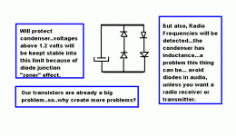
Voltage there can be very big if the amplifier have shorted output
shorted drivers or shorted VAS..... than, rail voltage or more than that will appear there.
Normally, voltage there is 40 milivolts....so...under normal work,e very insulating voltage can be used without problems.
But the one decided to use small condensers (ME) have to remember, after some accident, having enormous unballance of voltage...in those sittuations the output reach high voltage (more than zero)...that you may have to replace that condenser...it will be damaged by that higher voltage than normal.
During constructions, some transistor invertion or other mistake can produce this crazy voltage..giant off sets into the output...so..some attention may be needed.
There are folks that uses 4 diodes ...in series of two units....each serie inverted related the other...this is to protect that condenser...but we have Radio Frequency detection in those diodes..so... a good idea to protect a condenser against higher voltage than the unit you soldered there, may create you worst problems.
I do not suggest, do not use diodes.. but i am showing because that decision is up to my forum friends.
regards,
Carlos
Attachments
Average, I have no idea.
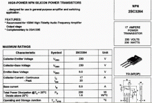
Minimum from the Sanken data sheets :
VCE=4V, IC=5A hfe 50
VCE=–4V, IC=–5A hfe 50
http://www.datasheetcatalog.com/datasheets_pdf/2/S/A/1/2SA1295.shtml
http://www.datasheetcatalog.com/datasheets_pdf/2/S/C/3/2SC3264.shtml
<chuckle> they cost two times as much as the Toshiba's so if the Dx-HiRes previously scored 94.5% then adding these will make it score 189%. Wow !
A pretty peacock perhaps 
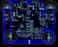
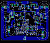
Those big capacitors have a major affect on the layout. I'm staying away from the board tonight, maybe ideas will spring afresh tomorrow.
If I get my parts order placed it should arrive on Friday. I'll build a board or two to test sizes etc and see how it all looks.
Carlos,
I've been so busy I forgot that you are building a working amp. How are things going ?
I went with these sizes as always someone will come around saying "can I use a brazilion volts with the PCB?"
The type of cap I will usehas pretty much the same width from 50V to 100V, with only the lenght varying... 1000uf also chosen as 63V, just for lower series resistance.... 220uf, is 13mm Vishay low ESR 63V.
The type of cap I will usehas pretty much the same width from 50V to 100V, with only the lenght varying... 1000uf also chosen as 63V, just for lower series resistance.... 220uf, is 13mm Vishay low ESR 63V.
Hi Nordic,
that PCB is looking pretty good.
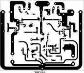
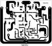
I particularly like the way the ground star is arranged as a tree, with the dirtiest returns towards the board edge and the cleanest at the top. Well done. You finally sorted the output trace to ensure the feedback signal actually measures the output.
The close coupling of the four front end transistors also looks good. I wonder of a radiation shield between the heatsink and these four transistors will be audibly better?
AndrewT said:Hi Nordic,
....
You finally sorted the output trace to ensure the feedback signal actually measures the output.
Hi Andrew,
I know nothing of the details, could you elaborate on this please ?
- Status
- Not open for further replies.
- Home
- Amplifiers
- Solid State
- Destroyer x Amplifier...Dx amp...my amplifier
