What has got fullrange to do with the match to near wall? Is it good that highs are modulated by cone excursion? 😀
I mean, it should be possible to design same kind of 2-way. Match for near is all about bass and low mids, nothing to do with how many "ways" there is.
what modulations? fullrange? they were designed to be satellites "for use in conjunction with bass systems"
it is there expressly written - SATELLITES - can't You read?
what modulations? fullrange? they were designed to be satellites "for use in conjunction with bass systems"
it is there expressly written - SATELLITES - can't You read?
Have to check those later more carefully. Documentations should be better though.
I'm not looking for any fullrange satellites + separate woofer sections, what so ever. Ordinary 2-way/3-way with decent bass without sub(woofers). Fullrange driver don't work for me (music taste etc).
so You can't see? this is touching too, and I am really sorry for You 😱
but OTOH surely You must have Your legendary (hyper)acute hearing partly because of that 😛
so, theVS300? what was the acoustic-center-of-the-speaker-to-boundary distance in their case? (please ask someone to help You)
because in Jordan JX53 array it was just about 5.5 cm, and the speakers were also by design 60 degrees toed-in, and they were designed to spaced widely and they were satellites to be supported by appropriate subwoofer(s)
ask anyone who can see to verify my claims, I have posted link to original construction plans
In that case the (first) dip would be at 3.1 kHz and the propagation loss would be even smaller due to the small path difference, possibly resulting in a stronger dip. The time delay is also virtually zero, so any measured comb filtering will probably be audible as well. The only thing that comes to the rescue is driver directivity. In this case the dip is also not corrected, unlike the VS300. Do you have measurements of this system so we can compare?
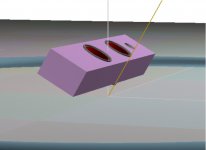
For those that are interested, I started the VS design with a model in the the excelent program Leap, Cabinet Shop. It lets you define a cabinet's dimensions and it does a full diffraction based model. It also lets you apply boundary conditions so I placed the unit in front of an infinite wall and it would then simulate the reflected image unit and the interference between the two.
The image shows a simple square box with two appropriately sized woofers. The system is angled inwards and all simulations and later measurements are taken on a 30 degree inwards axis.
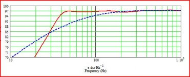
The two curves are of the simulated woofer box combination in free space (the dark curve) and the same system simulated against the boundary. You can compare these to the real measurements in the previous post. Correlation is quite good.
Note that this is the woofer response only (a low pass network is part of the model). You can see a hint of the upper frequency nulls but they are very minor and are in the stop band so the tweeter would hide them. The first dip is the primary concern.
This was an onwall "plasma TV" speaker, but a bookshelf system near the wall would give identical performance but with the dip at a proportionally lower frequency. Different cabinet tuning could help slightly but, really, EQ is required to effectively deal with the wall bounce.
Regards,
David S.
The image shows a simple square box with two appropriately sized woofers. The system is angled inwards and all simulations and later measurements are taken on a 30 degree inwards axis.
The two curves are of the simulated woofer box combination in free space (the dark curve) and the same system simulated against the boundary. You can compare these to the real measurements in the previous post. Correlation is quite good.
Note that this is the woofer response only (a low pass network is part of the model). You can see a hint of the upper frequency nulls but they are very minor and are in the stop band so the tweeter would hide them. The first dip is the primary concern.
This was an onwall "plasma TV" speaker, but a bookshelf system near the wall would give identical performance but with the dip at a proportionally lower frequency. Different cabinet tuning could help slightly but, really, EQ is required to effectively deal with the wall bounce.
Regards,
David S.
Attachments

Integrating speakers on wall is the only way to maximise the time gap between direct sound and the first room reflections.
- Elias
- Elias
Even though English is my first language, I'm not as literate as I should be, or could be. I blame the education system and flooders for making me this way.can't You read?
Even though English is my first language, I'm not as literate as I should be, or could be. I blame the education system and flooders for making me this way.
perhaps You mean Flodders made You illiterate? 😛

Integrating speakers on wall is the only way to maximise the time gap between direct sound and the first room reflections.
- Elias
but which wall? rather not on the front wall unless the speakers are heavily toed-in, like 60 degrees as in Jordan's array system
better on side walls as in Beveridge
In that case the (first) dip would be at 3.1 kHz and the propagation loss would be even smaller due to the small path difference, possibly resulting in a stronger dip. The time delay is also virtually zero, so any measured comb filtering will probably be audible as well. The only thing that comes to the rescue is driver directivity. In this case the dip is also not corrected, unlike the VS300.
at 3.1 kHz reflection is perfectly specular - angle of reflection equals angle of incidence - now take a look at Jordan's array, imagine it on wall and think where would the sound reflected off the front wall go? Would it be towards the listener to interfere with the direct sound and create dips and ups or not?
Integrating speakers on wall is the only way to maximise the time gap between direct sound and the first room reflections.
- Elias
And one wall reflection/cancellation less. 😉 Most important, less cancellation in midbass/low mids. Cancellation which goes higher, you can absorb unlike bass region.
what modulations? fullrange? they were designed to be satellites "for use in conjunction with bass systems"
it is there expressly written - SATELLITES - can't You read?
Satellites are on the sky.😀
Phase, Time and Distortion in Loudspeakers
"Naturally, if the number of drivers is reduced, the bandwidth they must cover is much greater - ever wondered why some (many?) large 2 way systems just don't seem to cut it? One of the biggest problems (and rarely spoken of) is intermodulation. If a cone is moving back and forth reproducing a low frequency, as well as 'jiggling' back and forth simultaneously reproducing a higher frequency, what will happen to the high frequency?"
separate bass systems, and you'll have many new problems...
Satellites are on the sky.😀
What are Satellite Speakers?
separate bass systems, and you'll have many new problems...
turn You equipment off and then You have no problem 😛
Far enough to create a dip at 500Hz.
Who can answer the question?
David S.
According to Roy F. Allison's 0.3x wavelength rule for suckout, that would be around 180mm - 200mm for that dip.
Attachments
Hi Alspe!
This is a question bothering me too.(to remove back wall dip).
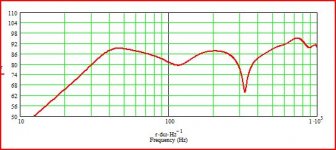
Here is too picture. One pure simulation without wall and foor.
And the other is with boundaries.
That 300Hz dip is from the floor and that wide one in 120hz is backwall, and it is WERY audible
VP
This is a question bothering me too.(to remove back wall dip).
Here is too picture. One pure simulation without wall and foor.
And the other is with boundaries.
That 300Hz dip is from the floor and that wide one in 120hz is backwall, and it is WERY audible
VP
Attachments
According to Roy F. Allison's 0.3x wavelength rule for suckout, that would be around 180mm - 200mm for that dip.
Very good. It is simply related to the distance between the source and its reflected image source.
At a frequency where the source and its reflection are half wavelength delayed they cancel and give the null in the curve. With a 1/4 wave spacing off the back wall the reflected speaker image is exactly 1/2 wave behind the source at the frequency of the null. (1/2 wavelength delay = maximum cancelation.
Allison was calculating the power response of a woofer against a boundary so he was integrating around a sphere. That is why he shows a dip at 0.3 wavelengths off the surface rather than the usual 0.25. 1/4 wave at 500 Hz is about 168mm.
Finally, since my simulations and measurements were done at a 30 degree inward angle you should divide the computed distance by cos(30) so I would calculate about 190 mm from woofer to wall to give the 500 Hz dip.
David S.
Don't do it!
have no fear! He won't cause He's still "in awe" for sure
now make calculations for Jordan on-wall JX53 array
Do you think that Jordan is the only driver which can do that? Are in some kind of Jordan marketing group?😀
JX53 seems to be pure midrange, and being more specific, upper midrange. Recommended XO around 200-500 Hz so you really have to design bass units which carry at least 3, maybe 4 octaves. Array of four fullranges bring more problems like phase cancellation.
- Status
- Not open for further replies.
- Home
- Loudspeakers
- Multi-Way
- Designing principles for near the wall-speakers