That´s a fine looking piece of hardware!
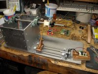
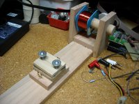
My own machine has a slightly more pronounced "ghetto" look, to say the least... Aside from that, it works surprisingly well as long as I enter the correct wire diameter (measured with micrometer) and assures that the surface to be wound upon is smooth enought.
Ok, I´ve wasted huge amounts of magnet wire on failed transformer projects the last few weeks but that has more to do with me raising my ambitions too quickly rather than with any shortcomings of the machine. I should of course have started with a few simple chokes and coils rather than trying to make a pair of sectioned PP output transformers...😱
Anyway, me and the programmer is currently working on a speed control for the spindle and traverse. Not much luck so far, I can get the speed down to zero but there us no useful range between zero and full speed. We´re working on it, slowly.
I´ve also ordered some parts for the wire tension servo mechanism. Instead of only using a stepper with shorted (or DC-magnetized) windings as a brake I´m giong to let the Arduino drive that stepper forward in the exact pace to keep the spring loaded "dancer" in a preset position. Might require a lot of coarse language to make this mechanism work...
Slow Progress
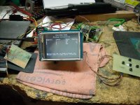
Well, the four line display got real crowded so I switched to a TFT display.
Unfortunatly this does not solve my synchronization problem. Depending on the number of turns and wire size, either the spindle will stop before the traverse, or the traverse will stop before the spindle. I can't seem to get them to stop together. It is a linear error.
I'm about to make a correction equation that will fudge them into synchronization and ignore it.
I can print the wind parameters before it starts winding, and everything looks correct. The only thing I can see is the possibility of the acceleration throwing it off, but I'm seeing a 14% error in 500 turns (not a likely configuration,but still it is an issue) and that is way too much for acceleration to account for.
Attachments


cantan, this is a thread about designing/constructing a trafo
please open a thread with your question
with appropriate thread title you might get answers to your question
when you have opened a thread I can move your post to there

moderation
please open a thread with your question
with appropriate thread title you might get answers to your question
when you have opened a thread I can move your post to there
moderation
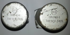
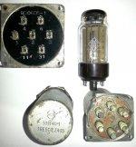
Output transformer from RCA 76-B5 broadcast mixing console (1939-).
"The output transformer is 901740-1 . The DCR readings are 2.64Kohms and 212ohms."
tinitus: move this post too.
"The output transformer is 901740-1 . The DCR readings are 2.64Kohms and 212ohms."
tinitus: move this post too.
After beating my head against the wall for nearly two months, I think I finally found my problem.
I updated the Arduino compiler from 1.04 to 1.05, and updated the AccelStepper library from 1.20 to 1.35 and the problem decreased by an order of magnatude. I'm now getting a total error at 300 turns of less than one turn, which may well be due to acceleration synchronization.
Now to go back and clean up the mess I made of the code trying to figure out what I was doing wrong and then I can work on the acceleration factors.
Good to see that you are making progress. I use cheap stepper driver/controllers between the arduino and the steppers, allowing the motors to run very smoothly thanks to microstepping. The arduino just sends pulses to the drivers, 3600 pulses per revolution of the spindle and 40 pulses /0,01mm traverse IIRC.
Well, it has been almost a year since I started this journey.
I've not posted for awhile, but have been working in the background on rare occasions when the mood struck.
I've found the limitations of using the arduino MEGA-2560 with AccelStepper (Insufficient horspower) and have managed to get someting that I think will work, although I had to strip out some features.
For my first transformer I'm going to attempt a ParaFeed output transformer for a headphone amp.
I'll be using EI-85 cores recovered from line transformers with home made bobins.
I've settled on and interleave of three primary segments and two secondary segments.
Primary is 1200 turns of #34 AWG wire in three segments of 300, 600, 300, and 150 turns per layer. Secondary is 156 turns of 34SWG wire in one layers per segment. Secondaries will be wired in parallel for a turns ration of 7.7:1 to drive 300 Ohm headphones.
I'm in a quandry as to how to wind the segments bassed on Patents by Hafler and others.
The writings I've found are for push-pull transformers and I dont' see how to directly apply the works to a SE Transformer, so I'm going to take a stab and go with Primary L to r, Secondary R to L, Primary L to R, Secondary R to L, and the final primary L to r.
I will experiment with how the secondaries are wired once the transformer is finished.
1. This was a trial run to test the winding tensioner. It looks good.
2. Close up of wire feed and tensioner.
Attachments

Last edited:
1500 turns in 10 layers
I finally wound the coil tonight.
First try last night was a mess.
I ended up using Bamboo paper instead of tissue paper as it is stronger. Craft Paper is "Right Out", as it is way too stiff.
As is, it is pretty poorly wound but it will work for a first pass to get some measurements.
I'll have to figure out how to bond out the leads and try to keept them straight.
Attachments


Hope it measures well, it would be refreshing to know that IT transformers aren´t as hard as they are said to be.
This is going to be an output transformer for a headphone amp. I decided to make it first to learn a little before I try an IT transformer.
It is going to be a ParaFeed output, so I don't have to gap the transformer.
It is going to be a ParaFeed output, so I don't have to gap the transformer.
oh ok, should have read before posting.
With regards to the winding direction I don´t think it is crucial in such a small transformer because capacitances will be small anyway, aim to reduce leakage inducance and that´s it (which you alredy did sectionalizing). For Parafeed you need really high inductance, I presume you´re going to stack the core 1:1? Equivalent gap is the smallest with 0.0005 inches
With regards to the winding direction I don´t think it is crucial in such a small transformer because capacitances will be small anyway, aim to reduce leakage inducance and that´s it (which you alredy did sectionalizing). For Parafeed you need really high inductance, I presume you´re going to stack the core 1:1? Equivalent gap is the smallest with 0.0005 inches
Yes, interleaved E/I core so the gap is the equivalent gap.
One thing I noticed is that the bobbin has been compressed slightly. This is something I will have to compensate for in the future, or use stronger bobbins.
E cores are difficult to insert, where they were easy to insert before winding.
Winding resistances are :
1 - 27.3 Ohm
2 - 95 Ohm
3 - 35.3 Ohm
Secondaries are:
1 - 14.8R
2 - 18.1R
Primary Inductance without the core is:
1 - 1.97mH
2 - 23.58mH
3 - 3.3mH
Secondaries:
1 - 0.6mH
2 - 0.77mH
HiPot all primaries to all secondaries failed at 2.4KV
Retest at 2.1KV passed.
1 - 1.97mH
2 - 23.58mH
3 - 3.3mH
Secondaries:
1 - 0.6mH
2 - 0.77mH
HiPot all primaries to all secondaries failed at 2.4KV
Retest at 2.1KV passed.
Is this possible? 10Hz to >100KHz ?
I finished putting the laminates back in the transformer, and the measruements I'm getting don't seem right.
I wired up the transformer and measured the leads for polarity to make sure I wired it correctly. I wired the secondaries in parallel, and the primaries in series without flipping the segment sequence around. ie, I wired the innermost primary section inner lead to ground, and the other end of it to the middle primary section, and wired the middle primary to the outtermost primary section.
I loaded the secondary with a 330R resistor since it is designed for 300Ohm Headphones.
I used an HP 3311A function generator as a source set to the 600R output.
I monitored the input voltage to the transformer and the output across the load resistor with two channels of an oscilloscope.
It is flat out past 100KHz and starts increasing below 200KHz, where it is it is up by 1.68dB.
300KHz +1.68dB
300KHz +6.3dB
380KHz +9.54dB (Peak)
400KHz +9.33dB
500KHz +3.9dB
600KHz + 3.9dB
700KHz -0.64dB
On the low end it is flat down below 10Hz and starts to saturate around 4Hz, although it is difficult to tell as the source is distorting as well.
Could the transformer really be that good (aside from the horrendous peak at 380KHz) ?
I'll take it in to work tomorrow and try to measure primary inductance and see how it goes.
Turns ration ended up at 6.667 : 1 instead of 7.7 : 1 so I messed up a layer count somewhere.
Last edited:
- Status
- Not open for further replies.
- Home
- Amplifiers
- Tubes / Valves
- Designing an Interstage Transformer