there are even
Add component: BASIC-> BASIC_VIRTUAL -> VARIABLE_CAPACITOR_VIRTUAL
which basically works the same as POTENTIOMETER as told in prev post
this can be useful, interesting, for example for selecting Compensation Capacitance in amplifier
Add component: BASIC-> BASIC_VIRTUAL -> VARIABLE_CAPACITOR_VIRTUAL
which basically works the same as POTENTIOMETER as told in prev post
this can be useful, interesting, for example for selecting Compensation Capacitance in amplifier
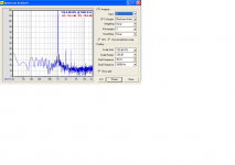
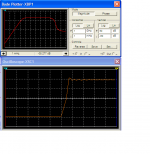
Comparing your FFT to my simulated in post above we see very much similarity 🙂 🙂
In fact it is close to a fingerprint!
3rd harm is a little a little below 2nd and the rest (>= 4th) is very much lower.
2nd -76.4 dB
3rd -78.0 dB
4th -98.0 dB
I would be happy with a power amplifier where high harmonics is -100 dB and lower.
Depends a bit of level of output power.
If your graf is from a higher Watt output, these figures are really good.
Now, if you could post a more easier to look at image
of only your EC (Bob Cordell error correction), maybe he would comment.
I suspect low levels of higher harmonics can be the result of this EC.
Regards 😉
Thanks lineup!
I managed to get slightly better figures after having played with bias and fine tuning the EC network (also reduced the emitter resistances of the EC trannys), but actually not much better (1-2 dB) than the other prototype using 2SJ201/2SK1530 without EC. Thats what puzzles me, the EC circuit seems to work ok as it regulates bias and I can easily find the best settings for the resistors. I think there should be a greater improvement using the EC. Perhaps just adding the cascode FET driver to the non EC prototype would improve it beyond this one.
I cant say exactly what power was used in the measurement above, but I can check tomorrow. Roughly about 10 watts into 4 ohms, and definately the same for both amps.
I will upload the schematics soon.
🙂
This shows maybe, that the EC does not work as effective as you like.
At a realtively high output (10Watt) the amplifier has very low H3, even without EC.
A good amplifier, I would say.
At a realtively high output (10Watt) the amplifier has very low H3, even without EC.
A good amplifier, I would say.
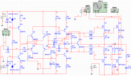
I also think I should see a larger improvement from using the EC. You´ll laugh when you see the original schematics with the 2SJ201/2SK1530....
Here it is, the original non EC amp, except the real one uses 2SJ201/2sK1530. I don´t have them in my Multisim.
Also, small signal transistors in the real prototype are:
2SC2389
2SA1038
drivers 2SD1812 and 2SB1818
Of course, there are plenty of ways to improve this minimalistic amp, but as seen it performs ok already, with H3 at about -100 dB.
Cascoding the drivers is probably the easiest way to gain more performance, but I´ll try to do something with the differential inputs too.
🙂
Attachments
Apart from the Candyman ?
NP mentioned a number of years ago that at the time he left Threshold with his "IGBT-Threat or F-Menace" paper, they were building Toshiba GT20D101/201 IGBT T-series with Hawksford/Cordell error correction overthere.
And we all know what happened to the T-series. (i hope)
NP mentioned a number of years ago that at the time he left Threshold with his "IGBT-Threat or F-Menace" paper, they were building Toshiba GT20D101/201 IGBT T-series with Hawksford/Cordell error correction overthere.
And we all know what happened to the T-series. (i hope)
As you have MOSFET without drivers = VAS drives Output Transistors,
To increase gain a little bit:
Connect Collector Q4 to Emitter Q1 and same on the Q6 side.
If uyou need, Reduce R1 R2 (100 ohm) to keep the Current Level in the VAS stage.
This 'trick' to feed the inverted input Transistors to Emitter in VAS
can give distortion improvement to an amplifier,
as well as the obvious increased Open Loop Gain.
I have done some comparing simulation tests some time ago.
Comparing the normal (Collectors to V+) and this idea.
Among those that have used this way is John Curl in some of his amplifiers.
Lineup
I do not know how much more gain you will get.
In my test circuit I used same current level for all 4 input transistors
as for the VAS stage.
As I recall something like 2.5 mA/transistor
As you use 'only' ~0.3 mA in each input transistor and ~8 mA in VAS,
you probably do not get that much extra gain.
But you can try to see if there is any positive effect.
I am going to increase the current through all the stages to improve slew rate anyways. Interesting that you suggest the extra positive feedback, as it turns out this is the way the prototype was wired almost 10 years ago, I just forgot and drew the schematics incorrectly.
By the way, are the Toshiba FETs still in production? Perhaps there are even better ones available now.
🙂
By the way, are the Toshiba FETs still in production? Perhaps there are even better ones available now.
🙂
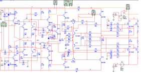
This is the latest schematic I´m testing at the moment. Trying to stabilize the entire amp as I have some problems. I would appreciate any input, and hope for better ways to stabilize without loosing too much slew rate. The EC OPS seems stable itself, but the rest of the amp tends to oscillate.
I´ve been playing around with small caps around the VAS, and it helps but not without paying the price of reduced speed.
Here´s the ms8-file if anyone wants to simulate it 🙂
http://www.autostock.se/download/?FILE_ID=EC amp.ms8
I´ve been playing around with small caps around the VAS, and it helps but not without paying the price of reduced speed.
Here´s the ms8-file if anyone wants to simulate it 🙂
http://www.autostock.se/download/?FILE_ID=EC amp.ms8
Attachments
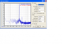
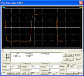
I think I might have found the source of instability, but haven´t tested in real life yet. Simulating square waves at 20kHz revealed parasitics, and I added two small caps around the VAS to stop the oscillation. Further sims and adjusting the currents resulted in better slew rate and bandwidth as well. 🙂 THe pic shows the simulation at 20 kHz with a time scale of 1 uS and 20 volts/square. f3 is now slightly above 2 Mhz.
I updated the ms8-file above so you can simulate it if you want to.
I updated the ms8-file above so you can simulate it if you want to.
Attachments
I decided to have another go with this amp, but now without the EC network. I get fairly good results without it so I don´t find it worth the extra complexity to involve it really.
One thing I would like to know is if there is an exact way of measuring the slew rate of this amp. I have attached the ms8-file if anybody wants to try it.
🙂
/Rikard
One thing I would like to know is if there is an exact way of measuring the slew rate of this amp. I have attached the ms8-file if anybody wants to try it.
🙂
/Rikard
Attachments
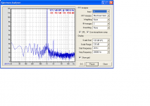
Forgot to say, the ms8-file uses IRFP240/9240s instead of the Toshiba 2SJ201/2SK1530 I use in real life. Anybody knows if there are any major differencies concerning the speed of these devices?
Thought I might upload a pic from the simulated 150 kHz squarewave at almost full swing. Load is 3,9 ohms and waveform measured after the output coil - which I had to almost short with 0,15 ohms to obtain the best slewrate. As I interpret the screenshot I´d say it´s about 300 volt/us.
🙂
🙂
Attachments
so that calculates to a power bandwidth of about 1.2Mhz. have you tried simming it with a 10n cap across the load? remember that's the reason for the output choke, to isolate the output from stray capacitances across the output (speaker wires, etc), and minimize the chance of oscillation.
the J201/K1530 are lateral MOSFETs and the IRFs are verticals, big difference in operating characteristics
the J201/K1530 are lateral MOSFETs and the IRFs are verticals, big difference in operating characteristics
Last edited:
- Status
- Not open for further replies.
- Home
- Amplifiers
- Solid State
- Designing amp with 2SJ201/2SK1530