Scott, could you divide the flat gain trace from the RIAA preamp to normalize out the "imperfect pinkness" and mask the resonance at 14K? Just a thought, not a request.
Scott, could you divide the flat gain trace from the RIAA preamp to normalize out the "imperfect pinkness" and mask the resonance at 14K? Just a thought, not a request.
I could, I'm set up for a round of measurements. I just tried the Telarc Omni disk and the pinkness is better, so much so that I'm wondering if these test LP's are good for anything. Maybe we should all get a ceramic cartridge that plows through the middle of the RIAA and have another glass 🙂. I'll try the Feickert one next.
Could be Lucky's right these tracks might have been -10dB and -20dB on the different LP's. If that was enough for +-1dB differences it's almost a why bother.
First error found, I set the un-pinking filter to 30dB for 4 decades which makes the average better. I'm still seeing sizable differences between disks.
I see magenta and cyan not pink and blue. Is my colour vision/monitor cal that far out?
Jeez Bill next time I'll make note of the exact Pantone colors. Since I ran a press shop for years I understand but the masses get it I hope.
I see magenta and cyan not pink and blue. Is my colour vision/monitor cal that far out?
You also have "colour" spelled funny.
Here in Maine we don't have Magenta or Cyan. (Except when I have to sort-out inkjet cartridges.)
I agree his colOrs are not sky-blue or euro-skin pink. (But didn't I read recently that we had no word for "blue" until a few hundred years ago?)
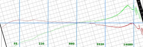
Pink noise goes down with 3dB/oct on a linear FFT scale. In your images you have 10 octaves, so after Riaa you should have a slope of 30dB over this range.
Looking at the blue Riaa line, this is true for most of the FR.
Because after depinking the Riaa line is not flat as to be expected, you have probably processed with the wrong slope.
Hans
Looking at the blue Riaa line, this is true for most of the FR.
Because after depinking the Riaa line is not flat as to be expected, you have probably processed with the wrong slope.
Hans
Jeez Bill next time I'll make note of the exact Pantone colors. Since I ran a press shop for years I understand but the masses get it I hope.
I was only being partially flippant. My red/green deficiency is such that certain colours just don't parse.
@PRR you also have muffins which are actually cup cakes. A muffin is toasted and and buttered 😛
Scott,
I have "depinked" your curve in Photoshop.
As you can see, over a large part of the FR it is within +/- 3dB, it's not that bad.
You have used a high impedance input on the 2i2.
But it would be interesting to see what happens to your 14Khz Grado bump when using the 3K Ohm Mic inputs.
When you can give me the Lcart and Rcart of your Cart, I can try to find some optimum for your digital filter.
Hans
Attachments
Scott,
I have "depinked" your curve in Photoshop.
As you can see, over a large part of the FR it is within +/- 3dB, it's not that bad.
Hans
Actually those plots are 30dB (3 decades) my "mistake" was wishful thinking and mistaken. The tilt still bothers me. And as I mentioned 4 different test records give 4 different slopes. And even worse the crosstalk vs frequency on them is dramatically different. I've been working with less than the best software so I'm going to see if I can export some files to Python also.
I'm going to try some frequency sweeps to get to the bottom of this since we need to trust things are correct if we ever commit to the DIY test LP.
Right now the only take away is that the direct connecting works without any obvious noise penalty (at least for my MI cart).
Right now the only take away is that the direct connecting works without any obvious noise penalty (at least for my MI cart).
That's good to hear, that will save you the time to do some DIY for making a Phantom Buffer.
Hans
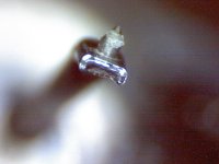
I needed my little piezo-brush to work off the gunk and try again. The frequency sweep and pink noise off of the same LP have greater than +-1dB discrepancies in FR so I wonder how much all this bother is worth.
Well keep the data as, if we ever get a good test record made we then can calculate calibration files for the other records from your data. The error bands on the B&K test records always concerned me.
Which is a long winded way of saying vital somebody did this, sorry it ended up being you 🙂
Which is a long winded way of saying vital somebody did this, sorry it ended up being you 🙂
Well instead of doing what I should have done I've opened a new can of worms. I've been hunting around for a way of recording SPDIF and so when I found a box of non-working M-audio microtrack II for £3 well I had to...
Turns out the batteries were made of cheese on these and all failed, so I stand a very good chance of getting a couple of working ones out of it. The bad news is that these were notorious for not having the lowest noise preamps and the Phantom power was only about 35V. A good candidate for messing around with 🙂
Turns out the batteries were made of cheese on these and all failed, so I stand a very good chance of getting a couple of working ones out of it. The bad news is that these were notorious for not having the lowest noise preamps and the Phantom power was only about 35V. A good candidate for messing around with 🙂
The complete sub-circuit in its most complex form with these added features is shown below. One could however leave the LT6203, only making it a bit more complex to find the right value for a feedback resistor but with hardly any effect on THD. So in its most basic form, only U1 is stronglyadvised !
Both the LT6203 and the LT1884 are duals,so only two SOIC packages have to be used, adding almost nothing to the neededPCB space.
There might be some concern that at powerup some uncontrolled current could flow into the Cart. However, because of thedifferential set up with no connection to Gnd, this is avoided and needs nofurther attention since being far under 100uA Imagine having a 10 Ohm Cart, that is used in current mode. 0 dB@10Khz, means ca. 5mV rms. In that case+/- 700uA peak flows through the Cart. So one can safely assume that start-upcurrents below 100uA are harmless.
Hello Hans
Can this method be used to avoid current to flow in the MC cart in this original circuit from Joachim Guerhard ?
We are using a resistor arrangement R15 31 37 to eliminate input offset but it is perfectible and your method seems a good solution.
Attachments
Interesting thread.
I assume one could compensate most of this in an dsp, so I guess I add an mm/mc input stage onto my adau1467 dsp board.
I assume some crosstalk is inevitable due to the mechanics of the disc itself.
Just for the sake of completeness.
But I am more keen on using a regular instrument amplifier.
Anyone considered putting the amp directly (very close) to the coil?
I have never given this specific area much thought during my life so please excuse me for being a noob.
Hi Ricardo,Hello Hans
Can this method be used to avoid current to flow in the MC cart in this original circuit from Joachim Guerhard ?
We are using a resistor arrangement R15 31 37 to eliminate input offset but it is perfectible and your method seems a good solution.
When your concern is current flowing into the Cart, there are many alternatives.
To start with, your own reincarnation of Joachim's original circuit with Fet's as input devices. Although producing a tad more noise, with 41nV RTI from 20Hz to 20kHz it is still way beyond what is minimally needed.
Notice the complete different design goals that Joachim and I had.
Open loop versus feedback
Single ended in and out versus Differential in and out.
Complete MC 60dB gain Riaa amp versus universal 10 or 20dB Head Amp.
Alone these items makes them fully incomparable, each of them having their own qualities.
So to answer your question, you will have to make up your mind what topology you prefer and what should be the dominant goals.
Hans
I see you misunderstood my question... what I wondered about was the possibility to place an opamp on the paradise IPS so to null the current flowing in the cart.
I was not asking how to mod the IPS of the paradise.
I was not asking how to mod the IPS of the paradise.
Now I will explain why I started all this.
I need a phono able to amplify and EQ MM carts and also MC carts.
As MM carts need 47k load I started this study to mod the paradise with jfet inputs.... after that I wondered if I could have a circuit for MC with jfet IPS and that is where you entered.
I learned a lot with your input so now I have two working circuits.
The first one is MC ready and the second one is good for MM.
Attachments
- Home
- Source & Line
- Analogue Source
- Designing a universal diff-in/diff-out Head Amp