SSassen said:
Oh my, what part of 'keeping objective comments about sound quality out of this discussion' did you not understand?
Best regards,
Sander Sassen
http://www.hardwareanalysis.com
Never did take no quite well. 😀 At least I stick to the issues not criticizing the person.
SSassen said:...and a proper dead-time setting for the MOSFETs, ...
Best regards,
Sander Sassen
http://www.hardwareanalysis.com
Sounds right to me.
soongsc said:
Sounds right to me.
I guess that was audiophile enough for you then? Shall we try to keep things ontopic from now on? Please?

Best regards,
Sander Sassen
http://www.hardwareanalysis.com
SSassen said:
I guess that was audiophile enough for you then? Shall we try to keep things ontopic from now on? Please?
Best regards,
Sander Sassen
http://www.hardwareanalysis.com
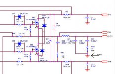
Let's look at this part of a Tripath amp for example. How would changing the output inductor improve the class D amplifier performance. People have previously posted core material parameters and windings. Does it make sense as a better output inductor?
Attachments
I'd put an additional "RF filter" after the main output filter in order to improve on RFI performance.
Remember that a simple LC filter is just a proper 2nd order lowpas IN THEORY.
I don't think that Lars' modulator is very susceptible to RF either. AFAIK it is a self-oscillating topology. Carrier-based amps are more susceptible to RF glitches (and restricted in terms of THD performance due to carrier residual).
And back to topic: Winding schemes that reduce the coil's parasitic capacitance will also improve the RF behaviour. One such scheme has already been mentioned by Lars.
Regards
Charles
The Tripath amp (from your posted section of the schematic) appears to use only pre-filter NFB. The output filter is therefore not part of the feedback path, so any problems with core non-linearities may have a measurable and audible effect on the output.
Charles,
Indeed, one other way is to compact the windings, so there's more windings per mm^2 and hence the inductance of the coil rises, thus we need fewer windings to end up with the same value in mH. Obviously the best way to accomplish this is to use copper foil, rather than copper wire. Hence a copper foil coil will allow you to wind it tighter and hence the coil will be more compact than one wound with copper wire.
As for the coil's capacitance dominating over its inductance at RF frequencies, this cannot be avoided, all we can aim to do is push the frequency at which the coil starts to exhibit this behaviour as far upward in frequency as possible. Hence keeping the parasitic capacitance low is a means to an end, yet as I mentioned we'd best forget about copper wire and use copper foil instead.
Best regards,
Sander Sassen
http://www.hardwareanalysis.com
And back to topic: Winding schemes that reduce the coil's parasitic capacitance will also improve the RF behaviour. One such scheme has already been mentioned by Lars.
Indeed, one other way is to compact the windings, so there's more windings per mm^2 and hence the inductance of the coil rises, thus we need fewer windings to end up with the same value in mH. Obviously the best way to accomplish this is to use copper foil, rather than copper wire. Hence a copper foil coil will allow you to wind it tighter and hence the coil will be more compact than one wound with copper wire.
As for the coil's capacitance dominating over its inductance at RF frequencies, this cannot be avoided, all we can aim to do is push the frequency at which the coil starts to exhibit this behaviour as far upward in frequency as possible. Hence keeping the parasitic capacitance low is a means to an end, yet as I mentioned we'd best forget about copper wire and use copper foil instead.
Best regards,
Sander Sassen
http://www.hardwareanalysis.com
phase_accurate said:
And back to topic: Winding schemes that reduce the coil's parasitic capacitance will also improve the RF behaviour. One such scheme has already been mentioned by Lars.
Regards
Charles
This is also covered in another thread which brings up the "banked winding" concept that reduces parasitic capacitance even more.
However, the new cored caused reduction in the necessary winding that probably made banked winding unnecessary. Has anyone actually measured this?
Ouroboros said:The Tripath amp (from your posted section of the schematic) appears to use only pre-filter NFB. The output filter is therefore not part of the feedback path, so any problems with core non-linearities may have a measurable and audible effect on the output.
Tripah engineers said the system would be unstable with post filter feedback. Even if post filter feedback was implemented, measureable and audible effects would still be there.
Tripah engineers said the system would be unstable with post filter feedback. Even if post filter feedback was implemented, measureable and audible effects would still be there.
Is this turning into a 'mod my tripath' thread now? Please stay ontopic!
Best regards,
Sander Sassen
http://www.hardwareanalysis.com

Gentlemen, please calm down. I don't know what it is with switching amplifiers, but the Class D forum currently seems to need as much moderator attention as the rest of the forums put together. Attack one another's arguments by all means, but not personalities. If it is your personal opinion that someone is an idiot who will never learn, then publicly saying so will not change them, and only sours the forum. If things don't calm down, I will be handing out extended Sinbin sentences freely, and banning will follow. You have ALL been warned.
SSassen said:Lars,
I disagree, you're just inserting another passive pole in the loop, in the feedback loop in case of post filter feedback. Either way this is a solution that seems to stem from a misunderstanding of the fact that a properly calculated control loop will behave properly with RF too, provided you have a proper layout and a properly wound coil. I hate to bring it up again as it makes me sound like a fanboy, but Bruno seems to be able to manage this quite well.
Best regards,
Sander Sassen
http://www.hardwareanalysis.com
This solution was proposed and is used by SONY in their S-Master amplifier.
Best regards
Lars Clausen
SSassen said:
Is this turning into a 'mod my tripath' thread now? Please stay ontopic!
Best regards,
Sander Sassen
http://www.hardwareanalysis.com
This is a practical example where people have actually changed the output inductor design. Is there a practical explanation whether the design is better or worse? It's okay to not respond if nobody knows the answer.
Lars Clausen said:
This is a common misunderstanding. The pre / post filter scheme has absolutely no bearing on PSRR. However open / closed loop has.
One way to get rid of the RF transmission problem in the coil, is to place a small open aircoil to 'eat' the high slopes before they hit the real filter coil. This way you can wind a normal simple filter coil without considering the RF properties.

I'm not sure how effective that would be, but it could certainly be simulated in spice if all spice models were available (a problem I constantly run into). Looks quite valid approach at a glance.

Here you can see why it works. This scope shot shows the 'blimp' enlarged, has a frequency of around 85 MHz. The first LC filter should have a pole at maybe 10 MHz, and thus will have 36dB attenuation at 80 MHz (3 octaves x 12 dB). Blimp 'poof' gone..!
Hi,
If anybody is willing to buy some spare MPP cores I would be interested in buying 4 from them.
Regards
John
If anybody is willing to buy some spare MPP cores I would be interested in buying 4 from them.
Regards
John
jkeny said:Hi,
If anybody is willing to buy some spare MPP cores I would be interested in buying 4 from them.
Regards
John
I probably could use two depending on what type you are getting.
What size cores are you guys looking for? I've already got some T106 MPP and Sendust on order (check the TI TAS5261 thread for more details), and if they look good when they come in I may order some more. I could even do a little group buy if anyone else is interested. T106 MPP are $3 each and T106 Sendust are $1.50 each from CWS.
On topic:
If copper foil is better, why not use copper foil with cores like Lars is using? The only difficulty I see with that is getting the foil connection out from the inside.
On topic:
SSassen said:Obviously the best way to accomplish this is to use copper foil, rather than copper wire. Hence a copper foil coil will allow you to wind it tighter and hence the coil will be more compact than one wound with copper wire.
If copper foil is better, why not use copper foil with cores like Lars is using? The only difficulty I see with that is getting the foil connection out from the inside.
- Status
- Not open for further replies.
- Home
- Amplifiers
- Class D
- Design of output inductor for class D amplifier