I have not found a way to test the real amplifier to prove the IV limiter actually works as well as the simulation model predicts. have you?
I have. I used a DC load as a load. I tried 2 situations:
- changing the input voltage of the output stage with a constant load (just as in the simulation). The DC load was a resistive load.
- changing the load conditions, by pulsing the DC load. The DC load was a changing current source.
Real world measurements where very close to the simulated results. It is very important to have good models of the transistors. I've got mine from ltwiki.org and they seem very accurate to me.
If the prot Q is thermally coupled to the output devices/heatsink, then you can make use of the changing Vbe due to temperature to change the limiting condition depending on the temperature of the surroundings. i.e. more current passes without limiting when Qprot temp is low and less current when high temp.
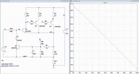
I did a quick simulation of how the VI limiter reacts to temperature. Very nice, as maximum current drops with temperature rise 🙂
Attachments
I did 30mins on it last night.
Had to add .include models because none of the transistors were included, not even the 1n4148.
eventually it recognised my .include, but still missing models.
So changed Q4 to bc550Cc, Q3 remained, Q1 & 2 to mjl1302c
and it ran.
But Ir11 ~84A
Q4 Vbe ~2V i.e. worse than hard on and still allows each output to pass ~41A.
Q3 Vbe ~1V
What am I doing wrong?
Can you explain what V3 pulse is doing?
Because I do a lot of simulations, I do not include the models. I've edited the standard libs in LTSpice, so I have all my transistors that are in stock available. I suggest you go to: Components Library and Circuits - LTwiki-Wiki for LTspice and pick the models that you need most. Place them in the lib/cmp folder. Transistors go in standard.bjt. I attached a sample for you.
View attachment standard.zip
View attachment standard.zip
I thought the standard library got overwritten when LTspice is updated.
How do you overcome the wiping out of all your additions?
I see 4 files in the .zip, but I can't open any of them.
How do you overcome the wiping out of all your additions?
I see 4 files in the .zip, but I can't open any of them.
I do not add them 🙂
After a update I put my standard libs in the cmp/lib folder. I found that the models included with LTSpice are not as accurate as those on LTWiki. As said, I only want to pick components that I have in stock.
After a update I put my standard libs in the cmp/lib folder. I found that the models included with LTSpice are not as accurate as those on LTWiki. As said, I only want to pick components that I have in stock.
After a update I put my standard libs in the cmp/lib folder.
Do the four files in the .zip go into the same lib/cmp folder, or into the same cmp/lib folder?Place them in the lib/cmp folder.
Will the new components appear when I click on device and see "pick new transistor"?
Last edited:
They go in the lib/cmp folder. Make a backup of the orginal files first. You must restart LTSpice.
- Status
- Not open for further replies.
- Home
- Amplifiers
- Solid State
- Design of my 120 Watt amplfier