Let's talk a little bit about resonant frequency.
Below my last iteration.
Every P is 2 layers and P/2 1 layer filling whole bobbin length.
Every S 1 layer filling whole bobbin length.
BW (-3dB) 5-179kHz and Fo=76kHz so less than half of the BW. Is it ok? or it should be outside the passband?
What Fo is typical is typical in your designs? and what is typical in commercial products?
Any comments about Q factor?
Last edited:

@Marek, assuming leakage inductance and capacitance are correct the first resonance at 53 KHz is of course correct but I don't believe you will get f-3dB at 179 KHz. In my experience, as the sqrt(Lleak/Cshunt) = 2.7K approx., your source resistance is less than 2K and the primary impedance better than 5K, the cut-off (-3dB) will be somewhere around 35KHz. FR should be smooth.
The earlier advice of not exaggerating with number of windings was sound. It doesn't give benefit beyond a certain amount. You are basically wasting more than 50% of the winding space with insulation.
The earlier advice of not exaggerating with number of windings was sound. It doesn't give benefit beyond a certain amount. You are basically wasting more than 50% of the winding space with insulation.
The Cshunt / Ls resonance is usually the less problematic one within an OPT, due to the fact it gets natural dampening because an OPT is loaded.
Dip resonances however are harder to predict, due to my findings they are activated with primary to primary section leakage coming from capacitance coupling between the sections. It gets severely activated when secondary sections with different capacitance difference to the primary are connected in series and are physically far away.
So rule of thumb is - connect secondary layers in series where there is no to little capacitance to the primary and are physically close, but parallel (or screen) secondary sections which are far away and have a big capacitance difference related to the primary.
A Q of 2.35 means you have a very peaked response and therefore f3 is so high. In reality, at such a high frequency the proximity losses will make a f3 of 179kc almost impossible unless you have really thin wire and very few layers per section (very small transformer).
Anyway, a Q of 2.35 is much to high, try to get something between 0.5 and 1.
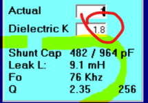
I calculated the real effective cap values of a pp transformer and the cap values this program gives are much lower than what i calculated. It would be good to know what formulas Yves used. I use the program but correct the C values by fiddling with the Dk to get closer to my calculated effective capacitance.
Also, if you use Nomex with a rated Dk of 1.6, this is measured WITHOUT winding compression. As soon as you wind a coil onto it the air pockets will be compressed, and the Dk rises 10-15%.
Just my observations
Anyway, a Q of 2.35 is much to high, try to get something between 0.5 and 1.
I calculated the real effective cap values of a pp transformer and the cap values this program gives are much lower than what i calculated. It would be good to know what formulas Yves used. I use the program but correct the C values by fiddling with the Dk to get closer to my calculated effective capacitance.
Also, if you use Nomex with a rated Dk of 1.6, this is measured WITHOUT winding compression. As soon as you wind a coil onto it the air pockets will be compressed, and the Dk rises 10-15%.
Just my observations
Last edited:
I think that as they have been designed the secondaries will be all in parallel.The Cshunt / Ls resonance is usually the less problematic one within an OPT, due to the fact it gets natural dampening because an OPT is loaded.
Dip resonances however are harder to predict, due to my findings they are activated with primary to primary section leakage coming from capacitance coupling between the sections. It gets severely activated when secondary sections with different capacitance difference to the primary are connected in series and are physically far away.
So rule of thumb is - connect secondary layers in series where there is no to little capacitance to the primary and are physically close, but parallel (or screen) secondary sections which are far away and have a big capacitance difference related to the primary.
@gorgon53 , capacitance is only a rough estimate and so is the Q. I would never change the design based on estimated capacitance unless I get silly high number. In this case is not. I think that there will be no peak at all in the FR within 70-80 KHz. If any peak will show up it will be second, third etc. resonances at higher in frequency than 53KHz. There will be no harm, especially if no ground feedback will be used, as the attenuation will be already significant where peaks happen.
Last edited:
I try to minimize capacitive loading and peaks and strive for a clean square wave response, especially with feedback, but everyone is entitled to his own preferred compromise's
Last edited:
Non just you. I only said that relying on a rough estimate is not a good reason to change the design if this is already looking ok. First test and then, in the worst case, re-do the coil. That is transformer winding normally. Best performance is rarely found doing simple calculations like these and relying on really basic modelling. If the parameters to change were leakage inductance or primary inductance they are much easier to estimate with good confidence.
Last edited:
What rough estimate? If the build up, dimensions, voltage distributions and dielectric properties are known the effective capacitance can be calculated, no rough estimate at all. And this then known capacitance can be entered into Yves calculator to get closer to reality results. So, what is the problem when adjusting the Dk accordingly is all that is needed?
You should realize that you are "only" estimating the static capacitance. Then you are not including other parasitic effects due how you wind the coil and how you do connections. Here you are also guessing what would the K of 10 layers of 0.1 mm insulators. And resin, if any? Good luck!
Another reason, leakage inductance can change a lot more by changing number of primaries and secondaries as it's inversely proportional to SQUARE number of the interfaces between primaries and secondaries. The more interfaces the less leakage, although such dependence on the square number of interfaces is partially reduced by the increased insulation. Static capacitance is proportional to the number of interfaces. Increasing insulation will reduce capacitance but in this case here more than 50% of the winding volume is already wasted with insulation!
Another reason, leakage inductance can change a lot more by changing number of primaries and secondaries as it's inversely proportional to SQUARE number of the interfaces between primaries and secondaries. The more interfaces the less leakage, although such dependence on the square number of interfaces is partially reduced by the increased insulation. Static capacitance is proportional to the number of interfaces. Increasing insulation will reduce capacitance but in this case here more than 50% of the winding volume is already wasted with insulation!
Last edited:
1nF is pretty good for such big transformer. If lower Q were my priority, the leakage inductance should be less without increasing C proportionally. The problem here is that the advantage of having so many sections is in good part wasted by the large amount of insulation. So if I had to re-design the transformer I would not use so much un-necessary insulation. 1 mm insulation between each primary and secondary is not necessary. Can be less.
In this case,1.5K plate resistance and 327R total DC resistance (primary resistance + secondary resistance multiplied by n^2) gives a total series resistance of about 1.8K.
The Xc (or the XL , as they are the same by definition at the resonance) is 3K. So Q=1.66. FR will be reasonably smooth, at worst it will show a modest bump. Square wave might show modest DAMPED ringing. Zero problem with no feedback and undetectable upon listening. It can still be used with feedback. I have seen good working tube amps with good amount of fbk and worse OPTs..
If I had 3mH leakage and 2 nF capacitance with same Rdc, I would have the resonance at 65KHz and Q=0.68. Square waves will be a lot better. Everything better.....Will sound better in zero fbk SE? Questionable.
Minimize capacitance? Yes but not at any expense. Trade-off rules.
Last edited:
For my taste this is bad operating point. GM-70 "shines" (soundwise and powerwise) at 1200V on anode with ~80mA DC current!Sure.
Popular operating points for GM70 are 800V anode, 100-120mA DC current.
Check the curves for grid requirements.
As for your project, I will follow it, maybe even interested later for purchase, depends upon 'real life' results.
Regards
@Marek, assuming leakage inductance and capacitance are correct the first resonance at 53 KHz is of course correct but I don't believe you will get f-3dB at 179 KHz. In my experience, as the sqrt(Lleak/Cshunt) = 2.7K approx., your source resistance is less than 2K and the primary impedance better than 5K, the cut-off (-3dB) will be somewhere around 35KHz. FR should be smooth.
The earlier advice of not exaggerating with number of windings was sound. It doesn't give benefit beyond a certain amount. You are basically wasting more than 50% of the winding space with insulation.
Its hard to relate to OPT_da frequency calculations but can you share how you calculated this 35kHz?
About number of windings. If I cut theme to 9 from last 17 parameters have deteriorated significantly:
Increasing insulation will reduce capacitance but in this case here more than 50% of the winding volume is already wasted with insulation!
What is the problem with "wasting" volume? Primary inductance is sufficient and wires gauge seems to be also oversized vs computed.
@ marek - did you answer whether this was push-pull or single device?
If single, your OPT will need an air gap and that will change the calculations.
If single, your OPT will need an air gap and that will change the calculations.
The more space you waste with insulation the less efficient is yourtransformer. Wasting less space with insulators you could reduce DC resistance of both primary and secondary of about 50%.What is the problem with "wasting" volume? Primary inductance is sufficient and wires gauge seems to be also oversized vs computed.
- Home
- Amplifiers
- Tubes / Valves
- Design of C-core nanocrystalline GM-70 output transformer