This is interesting. Are you happy with the performances ? Do you have an idea of the BOM cost ? Have you published the schema / PCB ? Or will you sell them ?
JMF
This evening, I was looking at the heatsink question. Especially because in my case I won't pull so much power from the amp. Max will be around:
- 60W in 8R
- 30-40W in 4R (about)
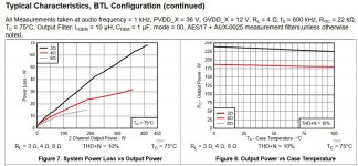
In Class D, most of the ouptup power is not dissipated inside the chip. Looking at the TPA3251 datasheet, there are some elements about the power losses (what is dissipated in the chip) vs the output power.
So with my max output power, I will have 15 to 20W loses dissipated in the chip. DSP and DAC power loses should fit in this enveloppe. This looks like the dissipation of a TO3 transistor (order of magnitude).
So in my specific case, the TI EVM heatsink is oversized (sized to cope with the about max 60W losses).
Junction-to-case (top) thermal resistance is about 0.2°C.
When considering continuous max power... Junction temperature 125°C. Let's say 50°C in the box, and 20W to dissipate => 3.75 °C/W
With 15W to dissipate => 5 °C/W
- 60W in 8R
- 30-40W in 4R (about)
In Class D, most of the ouptup power is not dissipated inside the chip. Looking at the TPA3251 datasheet, there are some elements about the power losses (what is dissipated in the chip) vs the output power.
So with my max output power, I will have 15 to 20W loses dissipated in the chip. DSP and DAC power loses should fit in this enveloppe. This looks like the dissipation of a TO3 transistor (order of magnitude).
So in my specific case, the TI EVM heatsink is oversized (sized to cope with the about max 60W losses).
Junction-to-case (top) thermal resistance is about 0.2°C.
When considering continuous max power... Junction temperature 125°C. Let's say 50°C in the box, and 20W to dissipate => 3.75 °C/W
With 15W to dissipate => 5 °C/W
Attachments
This is interesting. Are you happy with the performances ? Do you have an idea of the BOM cost ? Have you published the schema / PCB ? Or will you sell them ?
JMF
All files for this SMPS
And see this
Attachments
Last edited:
All files for this SMPS
And see this
Thank you drMordor. I will study this. I tried to use Chrome Google Translate feature to have a look at all your explanations on the design. Seems to work.
Any overall idea about the cost to build or by one ? I did not identified yet how you do for the transformer. "Home made" or "Off the shelf".
Thanks for sharing !
JMF
Any overall idea about the cost to build or by one ? I did not identified yet how you do for the transformer. "Home made" or "Off the shelf".
Thanks for sharing !
JMF
Transformer is "homa made" Epcos or any ETD 34
I have updated my wiki on the project, uploaded some pictures, information about soldering, board variant to declare in Arduino IDE and a basic Arduino sketch (one board controled by the onboard stm32).
This sketch is preliminary and may be optimized or be buggy or incomplete. It is just to give a flavour about what it needs to control the amplifier in a basic operation mode. To my eyes, it looks easy once the basic principles have been worked out.
Home * jmf13/NeatAmpTAS3251 Wiki * GitHub
GitHub - jmf13/NeatAmpTAS3251: Software part of the NeatAmp based on the TAS3251 chip
JMF
This sketch is preliminary and may be optimized or be buggy or incomplete. It is just to give a flavour about what it needs to control the amplifier in a basic operation mode. To my eyes, it looks easy once the basic principles have been worked out.
I just took a quick look on the code. Some comments:
- I would use defines or const int for pin assignment in arduino ide
- I think the read register function won't work, because the repeated start condition is missing (endTransmission without argument false)
- I would use the CFG_META_BURST option in the i2c write function. That reduces export data size from PPC3 software because not all addresses of subsequent registers/blocks are exported.
- is the analogRead fast enough to start the shutdown sequence at high loads (and therefore shorter ramp down of the supply voltage)?
- I would use defines or const int for pin assignment in arduino ide
=> may be
- I think the read register function won't work, because the repeated start condition is missing (endTransmission without argument false)
=> it is working. I can pull the values from the registers and capture them with the logic analyser
- I would use the CFG_META_BURST option in the i2c write function. That reduces export data size from PPC3 software because not all addresses of subsequent registers/blocks are exported.
=> can be improved, but the way PPC3 does structure the data does not use this
- is the analogRead fast enough to start the shutdown sequence at high loads (and therefore shorter ramp down of the supply voltage)?
=> I don't know. Even worse, I run the main loop quite slowly. I have no clue which response time would be suitable here. How long normally takes analog read to operate ?
JMF
To add to those points:
1) "const byte" is the best way to define pins, has to do with the compiler. Just a small detail:
Const vs #define - When do you use them and why? - Bald Engineer
2) endTranmission(false) keeps the I2C bus busy, which prevents another master from hijacking, which is not applicable in this case
3) You have to export your header file like a burst file in PPC (burst = 128 in the export menu). Then it will use the burst function, which can half your file size (and write time). In burst modes it keeps writing for sequential (see 8.3.7.2 Register Address Auto-Increment Mode in the datasheet).
4) This is for the VDD measurement right? I would keep a rolling average or something similar to keep the amp from shutting down during voltage drops at high load.
Thanks lutkeveld for sharing the tips for 1), 2) and 3).
Yes, 4) is for the voltage measurement. to detect that GVDD goes below 10-12V. In the EVM, this is managed by a TPS3802K33D that trips the uC and /RESET_AMP when coming low. So quite crude reaction.
Oh, by the way, I tested the amp (mono) on a Tannoy Berkeley. Listening level achieved easily with only 20V power supply. No humm with the ear on the speakers. Transparent, detailed, lot of dynamic. Far from being a full audiophile test, but promising.
I had jus a small heatsink drop on top of the TAS with co thermal paste. No Clip_OTW nor Fault. heatsink nor really hot.
The Tannoy are nor normally to be paired with this amp. Normally it is for my LX-Mini that need more power to deliver
JMF
Started to play with PPC3 and the DSP configuration yesterday evening. Half success... I tried to configure the thing with proposed 1.1 config mono => Lowpass filter to Woofer and highpass filter to Tweeter.
Downloading straight the thing in the board => only one channel working (seems to be the tweeter one).
Attempts with PPC3 sending the same thing to L and R are working. So it is no board problem.
I believe I miss something somewhere (potentially obvious). I post here in case it rings something to somebody.
JMF
I'd recommend to use a 2.0 process flow for everything except pbtl/mono configs.
I never had any issues with the 2.0 configs with tas5825m. I tried the 1.1 one time and I had some problems too.
I never had any issues with the 2.0 configs with tas5825m. I tried the 1.1 one time and I had some problems too.
Hi, I think that the file generated by PPC3 is wrong at leat in two points in 1.1 Mode:
- input mixer
- output crossbar.
I posted on e2e, but no answer yet.
I wonder how is selected in those DSP the "Process Flow" (there are 6 of them on the TAS3251). I did not found the information in the datasheet, nor the SLAA799A. It is to check if my assumptions about the workflow used in mode 1.1 is the "3" as I expect.
Would you know ?
JMF
Feedback from e2e: my issues may be related to the fact that I don't have the last version of PPC3 and TAS3251 module.
Unfortunately, there is an IT glitch that prevents updating PPC3, which should be solved... soon.
Wait and see,
JMF
Unfortunately, there is an IT glitch that prevents updating PPC3, which should be solved... soon.
Wait and see,
JMF
I have same issue from the very beginning of tests: the files coming from PPC3 doesn’t produce any sound. The files generated have some crucial registers ( for instance volume ones : Book0x8c-Page0x1E-Registers0x44 & 0x48) which set to zero rather than their default value (for instance 0x00800000, which is the value for 0dB, for the same volume register). But fixing these registers was'nt enough.
So I explored another way : being able to load the configurations described in TI doc SLAA799 : TAS3251 Process flows which are looking much better than PPC3 ones : values of the register looks like default value..
So, 5 of the 6 flows from SLAA799 document have been loaded from the .pdf to an Excel file , some data cleaning and formatting have been done and a VBA function has been written to produce PPC3 .h format file regarding the DSP configuration : Book 0x8c.
XL file attached contains : flows 1,2,3,4. Flow 5 is just loaded word Word/Acrobat, it is not usable since formatting hasn’t been done : I do not plan to use it for now.
As a result, the flows described in this SLAA799 are ok they do not mute the TAS and, IMHO they could be considered as a reliable starting point.
Zip file contains the XL file with macro. No harm : it's safe copy.
Attachments
Again AIM65, this is impressive work. You do not looks to be the type of person when it "just works".
Thank you for providing the tool and the macro. This will allow to make some experiments.
The good news is that with this work, the TI Biquad calculator or the miniDSP one : all pieces are on the table for an "open" configuration tool, and not being tight to the propriétary PPC3 one. May need some additional code to get the thing reasonably user friendly.
By the way Christophe, which versions of PPC3 and TAS3251 module do you have ? I have PPC3 v3.1.1 build 247 and TAS3251 v3.0.1. It seems that PPC3 v3.1.5 build 745 should be available when they will have solved theit IT issue.
JMF
Looking at the Registers, I have the impression, that in fact there is only one process flow, described in fig 41 of the datasheet, and that the "6 process flows" are only zooms on some of the blocks.
Each register seems to be associated to only one function. Each "process flow" only configure a subset of thems (leaving others to default values).
Is this correct ?
PPC3 and TI doc SLAA799 "TAS3251 Process flows" let think that you can only use a subset of blocks for a certain sample rate, that you have to "choose" the modules you use. I wonder if there is in fact a "technical limit" and sort of DSP overload, or if it is for better " functional understanding"...
JMF
Last edited:
Yes that is what it looks like. The flow configures how the data flows through a limited amount of blocks (probably due to a certain amount of available processing cycles).
From the one side it's pretty convenient to have certain flow for a certain usecase. But from the other side TI makes it very difficult for themselves by having to maintain all these flows.
You would think that it would be possible to just make one big control panel and choose how you want your data to flow and then have the flows implemented as presets.
Did you already test your PCB with having no flow selected? It should work that way as a regular 2.0 amp. Also pay proper attention to startup sequencing and correct I2C write functions.
Thanks Lutkeveld to confirm the understanding.
Yes I tested the amp with the "minimal config" from AIM65, and it works fine on the Tannoys 🙂
Next step is to implement the LXmini filter and use the TAS3251 in that active speaker config (initial purpose of the project).
JMF
Yes I tested the amp with the "minimal config" from AIM65, and it works fine on the Tannoys 🙂
Next step is to implement the LXmini filter and use the TAS3251 in that active speaker config (initial purpose of the project).
JMF
- Home
- Amplifiers
- Class D
- [design log] Neat 2x170W I2S in, I2C controlled, integrated DSP amp (TAS3251)