tiefbassuebert,
it`s hard to say, isn't it, complicated by the fact that THD has the propensity to be inversely related to perceived sonic values.
it`s hard to say, isn't it, complicated by the fact that THD has the propensity to be inversely related to perceived sonic values.
Until this day (since 30 years) I haven't found a review in a HiFi magazine with method for the measurement of distortions that show unique information, how the amp sounds.tiefbassuebert,
what THD values are satisfactory, according to who? tiefbassuebert,
it`s hard to say, isn't it, complicated by the fact that THD has the propensity to be inversely related to perceived sonic values.
Therefore I can't give answer to this question in generall.
But I know, that classical NFB amplifier topology like D. Self's "Blameless Amplifier" gives excellent THD result by simulation and real life measuring, if I choice the hard running mode (i. e. 1,5A idle current through the output devices)
In opposite of this - single ended topologies like Pass ZEN (I use first vaiation) gives no exzellent THD result by simulation and real life measuring.
If I check the audible character (both amplifiers operates at oversized power supplies), I note by the use of full range aera at all kind of speakers, that the Zen sounds better at the upper frequencies and the "Blameless Amplifier" sounds better at the lower frequencies (the different isn't extrem but clear noticeable by the operating aera below <5 watts).
By reducing the Idle current to 20 mA in the output of "Blameless Amplifier"
THD result by simulation and real life measuring dramatically worsen, also the sound character at the upper frequencies (harshness by voices, "S"-sounds comes heavily distorted) but still sounds better at the lower frequencies than the Zen (I guess below 500 Hz).
Refer at high frequencies above approximately 500 Hz, the above mentioned things correspond exact to the observations and descriptions of Mr Pass, to read about
http://www.passlabs.com/pdf/articles/seclassa.pdf
http://www.passdiy.com/pdf/zenamp.pdf
You don't tell about your components but I think, that you are not satisfied with your sound reproduction in your home. Perhaps you don't know what is to change.
Regarded the Densen circuit topology I have make by simulation six different variations
- without NFB
- with NFB connected to the output of VAS
- with NFB connected to the output of power buffer
all versions with 1,5A and 20mA idle current through the output stage
after the evaluation of all versions I will publish the THD/IM results and this one of damping factor frequency response
Last edited:
tiefbassuebertr,
Because there does not exist such a measurement method.Until this day (since 30 years) I haven't found a review in a HiFi magazine with method for the measurement of distortions that show unique information, how the amp sounds.
You still stated that " On one hand we see THD values that have nothing to do with high fidelity". Maybe those THD values do indicate high fidelity.Therefore I can't give answer to this question in generall.
The distortion mechanisms are explored in detail, making things predictable.You don't tell about your components but I think, that you are not satisfied with your sound reproduction in your home. Perhaps you don't know what is to change.
In Germany they still think that B350 is a class A power amp, have a look yourself.
This is taken from this website today: http://www.connectaudio.de/densen/0496429bc90c37106/0496429c1a0d31f11/index.html
Price tag 7.500€ pair.
B-350 Technische Daten
Leistung 1 x 125W 8 Ohm / 1 x 250W 4 Ohm - im Class A Mode 40 Watt an 8 Ohm
Lautsprecheranschlüsse 2 Paar pro Kanal
Siebkapazität 750VA
Netzteil 100,000 Mikrofarad
Abmessungen 44,4cm x 31,0cm x 6,4cm
Erweiterbar mit Saxo Frequenzweiche
There are another brand, that also claim by their mostly models, it's class A (here in Germany even "Pure Class A") The brand name is CEC (C.E.C) and the name of circuit topology "LEF (Load effect free). The developer is Mr. Carlos Candeias. Have a look to this URLs: Amp 3300R:
CEC AMP3300R
Amp 5300R (Amp5300R)
CEC EUROPE WEBSITE
The last model delivers 120W/8 ohms and 135W/4 ohms
Regarded this models I start a new thread for getting schematics:
http://www.diyaudio.com/forums/soli...r-lef-class-schematic-wanted.html#post1972358
If anybody can posted a schematic there, I can try to verify about simulation that claim
... to meet "all" your subjective criteria so on the one hand could I say it's must be approaching technical perfection, or on the other that "we just don't fully know" why vanishingly small distortions colour the sound as much as they seem 😉
This is actually not true, we should talk more about, what happens if one expects a certain degree of distortion and it suddenly is not there.
Some people still seem to think, that missing distortion is distortion sound wise.
I give you an example:
Let's measure the distortion of a 1m long RCA interconnect ! The THD meter gives 0.00001%, so it is essentially distortion free.
Do now all cables sound bad, just like the "bad" amplifiers having the same degree of distortion ?
Should we then add hysteresis to them (e.g. iron cores) to get a certain sound ?
IMHO amplifiers are by far the most senseless part within the chain to realize a certain "sound" idea, because they are at the electrically difficult border between weak signals (uWatts) and strong signals (Watts). To realize a proper amplification (e.g. with output transistors), while still creating a certain sound signature with the same devices is absolutely impossible, because such idealized devices simply don't exist (anymore) !
If you are doing so (like with a no feedback bipolar Class B stage), you have to expect that all the bad things of power silicon can be heard (thermal distortions, switching distortions, nonlinear behaviour of junction capacitances etc. etc.).
The only way to get rid of these effects is doing Class A at reasonable high bias currents and voltages and/or using some kind of substantial NFB (being local or global).
tiefbassuebertr,
why should a lab test and a listening session at Stereoplay be not contradictory (!!!). I give you some reasons:
1) Please consider, that the guy, who made the Densen test is the same, who recently completely sucked and blamed himself with his newly invented measurement method in the Brinkmann integrated amplifier test. I think he simply likes this grainy sound and wants to find any explanation, why such badly measuring amplifiers are sooo good. The Brinkmann amplifier is btw. the same working principle as the Densen.
2) Magazines live from advertising, so no tester would say a product sounds bad, if the manufacturer of this device makes big advertising or is a friend ...
3) Some magazine testers have simply worn out ears.
4) Are you still believing in Hifi tests ???
Last edited:
tiefbassuebertr,
why should a lab test and a listening session at Stereoplay be not contradictory (!!!). I give you some reasons:
1) Please consider, that the guy, who made the Densen test is the same, who recently completely sucked and blamed himself with his newly invented measurement method in the Brinkmann integrated amplifier test. I think he simply likes this grainy sound and wants to find any explanation, why such badly measuring amplifiers are sooo good. The Brinkmann amplifier is btw. the same working principle as the Densen.
2) Magazines live from advertising, so no tester would say a product sounds bad, if the manufacturer of this device makes big advertising or is a friend ...
3) Some magazine testers have simply worn out ears.
4) Are you still believing in Hifi tests ???
I think, this is the concerning Brinkmann amplifier:
brinkmann audio
Brinkmann Audio at Walrus Systems hifi website
and this the test from stereoplay, what you mean - indeed, same basic approaches regarded the circuit and similar THD results.
http://www.brinkmann-audio.de/inhalt/de/test/integrated_stereoplay5-09.pdf
and a more aggressive discussion than this here about the Densen:
Verstärkertest Stereoplay 5/2009 - stereoplay
PM-11S channel. 
Peek through the window Bingo time : C29-A12
Peek through the window Bingo time : C29-A12
Attachments
Last edited:
This is actually not true, we should talk more about, what happens if one expects a certain degree of distortion and it suddenly is not there.
Some people still seem to think, that missing distortion is distortion sound wise.
I give you an example:
Let's measure the distortion of a 1m long RCA interconnect ! The THD meter gives 0.00001%, so it is essentially distortion free.
Do now all cables sound bad, just like the "bad" amplifiers having the same degree of distortion ?
Should we then add hysteresis to them (e.g. iron cores) to get a certain sound ?
IMHO amplifiers are by far the most senseless part within the chain to realize a certain "sound" idea, because they are at the electrically difficult border between weak signals (uWatts) and strong signals (Watts). To realize a proper amplification (e.g. with output transistors), while still creating a certain sound signature with the same devices is absolutely impossible, because such idealized devices simply don't exist (anymore) !
If you are doing so (like with a no feedback bipolar Class B stage), you have to expect that all the bad things of power silicon can be heard (thermal distortions, switching distortions, nonlinear behaviour of junction capacitances etc. etc.).
The only way to get rid of these effects is doing Class A at reasonable high bias currents and voltages and/or using some kind of substantial NFB (being local or global).
tiefbassuebertr,
why should a lab test and a listening session at Stereoplay be not contradictory (!!!). I give you some reasons:
1) Please consider, that the guy, who made the Densen test is the same, who recently completely sucked and blamed himself with his newly invented measurement method in the Brinkmann integrated amplifier test. I think he simply likes this grainy sound and wants to find any explanation, why such badly measuring amplifiers are sooo good. The Brinkmann amplifier is btw. the same working principle as the Densen.
2) Magazines live from advertising, so no tester would say a product sounds bad, if the manufacturer of this device makes big advertising or is a friend ...
3) Some magazine testers have simply worn out ears.
4) Are you still believing in Hifi tests ???
You are just right.
And some people simply like distortion.
To me a non feed back underbiased class B stage is just about the worst of all, which also measurements clearly supports.
Heavy bias though is IMHO preferable to substantial amounts of NFB.
Last edited:
Off topic - sorry Guys
Good morning Jon - Help - I understand you are designing a rebuild of the Graaf GM20. I am very interested to hear how is the progress and what you have found. Vielen danke, Steve
Good morning Jon - Help - I understand you are designing a rebuild of the Graaf GM20. I am very interested to hear how is the progress and what you have found. Vielen danke, Steve
DM30
Hi all,
sorry for resurrecting an old thread, but yesterday my DM-30 started emittting strange noises from the loudspeakers. It is an old design, and was rebuilt my Mr. Densen in person (Tomas Sillesen) a couple of years ago (lifetime warranty).
Now, I'd like to ask whether are there any schema around and what would be a correct troubleshooting procedure and what steps should I follow?
Thanks for any help or hint,
Stefano
Long time ago I draw this Densen. The feedback is taken from VAS, not from output node. SMD parts.
Hi all,
sorry for resurrecting an old thread, but yesterday my DM-30 started emittting strange noises from the loudspeakers. It is an old design, and was rebuilt my Mr. Densen in person (Tomas Sillesen) a couple of years ago (lifetime warranty).
Now, I'd like to ask whether are there any schema around and what would be a correct troubleshooting procedure and what steps should I follow?
Thanks for any help or hint,
Stefano
P.S.: found this: http://www.diyaudio.com/forums/solid-state/136261-vintage-amplifier-repair-upgrade-manual.html
But some schema would definitely be of help, even in PM 🙂
But some schema would definitely be of help, even in PM 🙂
Hi all,
sorry for resurrecting an old thread, but yesterday my DM-30 started emittting strange noises from the loudspeakers. It is an old design, and was rebuilt my Mr. Densen in person (Tomas Sillesen) a couple of years ago (lifetime warranty).
Now, I'd like to ask whether are there any schema around and what would be a correct troubleshooting procedure and what steps should I follow?
Thanks for any help or hint,
Stefano
The marked term I don't understand.
Perhaps you mean shot-noise or flicker-noise.
If you observe this noise only by one of both channel, I guess, the input stage is faulty. Disconnect your preamp and connect chinch plugs with internal shorting bridge in your input sockets. If it no longer occurs, my estimate is right.
Otherwise an other reason causes this error. Schematic is necessary under all circumstances. Call Mr. Tomas Sillesen for asking.
Is it this model?
DENSEN DM-30
Attachments
Last edited:
First of all, thanks for your answer.
Perhaps in a few hours I'll be able to open it, post a photo and confirm but, if memory serves me well, it is the model in the picture.
First I heard a sort of some intermittent pauses in sound from one of the channel (right). After some seconds it repeated. I powered off and after a while I powered it on again. This time I heard something like white noise from the Left channel. So I turned it off fearing for my loudspeakers.
I listened at the pre headphones out and the pre seems working fine (at least till to the headphones out).
Of course the DM-30 was very hot (as it has been pointed out in the thread, it always runs very hot). Fault appeared after - let's say - 10 hours of low level listening. Environment temperature around 26°C.
Stefano
If there is no separate headphone amp section inside, I assume, that the speaker DC protection relay contacts contaminated or damaged (unwanted contact resistance, maybe highly variable).First of all, thanks for your answer.
First I heard a sort of some intermittent pauses in sound from one of the channel (right). After some seconds it repeated. I powered off and after a while I powered it on again. This time I heard something like white noise from the Left channel. So I turned it off fearing for my loudspeakers.
I listened at the pre headphones out and the pre seems working fine (at least till to the headphones out).
Stefano
In this case you must desolder/open the relay and polish carefully the contacts.
If a separate headphone amp section is inside, then the reason could also be a broken solder joint between the pre-out and poweramp-in (ckeck out burning aeras on your PCB).
that does not sound good. How much do you estimate the temperature (at approximately 50 degrees Celsius you burn just not yet).First of all, thanks for your answer.
Of course the DM-30 was very hot (as it has been pointed out in the thread, it always runs very hot). Fault appeared after - let's say - 10 hours of low level listening. Environment temperature around 26°C.
Stefano
Nevertheless - is the temperatur in this aera at 26 degrees ambient temperature (i. e. more than 20 degrees above ambient at low level) it is clearly too hot.
This means, you must replace all electrolytic caps.
Perhaps you can measure the idle current through the output stage and the voltage supply at Sanken's BjT power output devices.
Then we can calculate the idle loss power and the actually require heatsink values and compare to the currently exist heatsink size.
Last edited:
Perhaps my English is really poor.
I only meant that it was a warm day (about 26°C at home), but not the hottest.
BTW, I would be happy if I had to replace only elcos 🙂
I only meant that it was a warm day (about 26°C at home), but not the hottest.
BTW, I would be happy if I had to replace only elcos 🙂
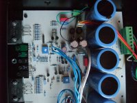
my DM30 inside
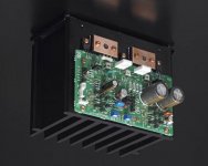
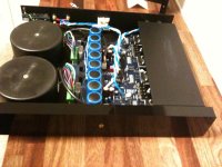
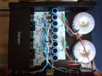
Here are shots of the inside.
The amp has been reworked by TS (so states a paper label behind it) so, I guess it might use newer parts than original one (the one in your photos that I remember before Densen previous repair).
Anyway, now at least one Elco leaked. As from the marketing materials each DM30 should have 80000uF splitted in 8 caps, so it's easy to know what is the needed capacitance. But what about the needed voltage?
I would clean everything, look for shorts, exchange caps (I fear all are needed)
Another dumb question: can you point me to where to learn how to properly detach (and reattach 🙂 ) transistors from the "heatsinks" (here is the case itself) without destroying them when they're coupled with thermal compound?
Kind regards,
Stefano
Attachments
Last edited:
Here are shots of the inside.
The amp has been reworked by TS (so states a paper label behind it) so, I guess it might use newer parts than original one (the one in your photos that I remember before Densen previous repair).
Anyway, now at least one Elco leaked. As from the marketing materials each DM30 should have 80000uF splitted in 8 caps, so it's easy to know what is the needed capacitance. But what about the needed voltage?
I would clean everything, look for shorts, exchange caps (I fear all are needed)
Another dumb question: can you point me to where to learn how to properly detach (and reattach 🙂 ) transistors from the "heatsinks" (here is the case itself) without destroying them when they're coupled with thermal compound?
Kind regards,
Stefano
Because I don't discover a relay I guess, there is no DC protector section for your loudspekers in use. By certainly kind of failures your voice coil of your speaker will be burn/damaged.
consequently, you may no longer operate the amplifier to a loudspeaker until remove all defective components.
Determine the supply voltage without connected speakers as follow:
Connect one plug of your multimeter to the neg (black) speaker terminal (DC voltage mode, 1000V aera) and the other both at the collector (center leg) from Sanken's 2SC2922 and 2SA1216 (MT-200 outline) The value of voltage must be the same, but with different signs.
If a CFP (Sziklai-Darlington) push-pull buffer is in use, you will read only a very low value (from idle current + CD offset).
Then you must use the emitter leg (right hand).
According this voltage you must choice the capacitors. If you measure 45V or below, use a 63V version. If you measure between 45V and 70V, use a 100V version. Capacity isn't critical - values between 4700 uF and 15000 uF are usual.
But watch out for the least possible value for ESR. Replace all electrolytic caps.
Mundorf is a good choice - go to
http://www.mundorf.com/deutsch 1.1/kondensatoren2.htm
http://www.mundorf.com/nationsite/italienisch/Condensatori-Amplificatore_ital.pdf
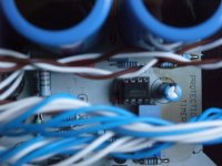
In front of both Sanken's 2SC2922 and 2SA1216 I discover 10 resistors in parallel mode. This reduces the parasitic (and unwanted) inductance. I don't identify the colors. If it is brown-black-black-gold, each resistor is a 1-Ohm version (at whole 0R1).
Please measure the voltage across one of this resistor. If you divide the value of voltage by 10, you read the value of the used idle current.
Concerning the disassembly of Sanken's 2SC2922 and 2SA1216 I can't give any advices, because I don't know the special futures that were used by assembly from Densen.
Last edited:
Thank you Jacco and Tiefbassuebertr,
I do hope my trusty Dynaudio Contours will survive the fault (yes, it was a Danish connection regarding output stage of the audio chain 🙂 even if with Mundorfs it would be German juiced 🙂 ).
I still have to measure voltages, but resistor colors seems to me brown-gold-black-black-red and I seem I see two areas on the board marked as "Protection Timer".
Thank you all, again,
Stefano
- Home
- Amplifiers
- Solid State
- Densen amp