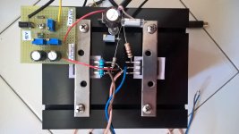
Thanks Antoniel for sharing your experiments with DEF. There are photos of my experiment with IRFP9240/IXTH16N50D2 and the measures, after about 60 minutes!!!:
Vds =+/- 23V
Vg1 = -1.76V (IXTH)
Vg2 = -4.55V (IRFP)
Ids = 1.28A
Voffset = < 20mV
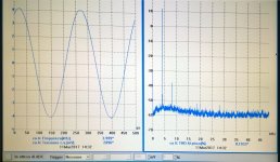
The circuit is the same as the post #43. the power supply (-12V) for Voffset adjust is separate and there is the bootsrap capacitor. Probably the distortion of DEF is lower. The generator (Tektroniks SG505) and the spectrum analyzer (PICO ADC212) add THD.
Vds =+/- 23V
Vg1 = -1.76V (IXTH)
Vg2 = -4.55V (IRFP)
Ids = 1.28A
Voffset = < 20mV
The circuit is the same as the post #43. the power supply (-12V) for Voffset adjust is separate and there is the bootsrap capacitor. Probably the distortion of DEF is lower. The generator (Tektroniks SG505) and the spectrum analyzer (PICO ADC212) add THD.
Attachments
Thanks Antoniel for sharing your experiments with DEF. There are photos of my experiment with IRFP9240/IXTH16N50D2 and the measures, after about 60 minutes!!!:
Vds =+/- 23V
Vg1 = -1.76V (IXTH)
Vg2 = -4.55V (IRFP)
Ids = 1.28A
Voffset = < 20mV
The circuit is the same as the post #43. the power supply (-12V) for Voffset adjust is separate and there is the bootsrap capacitor. Probably the distortion of DEF is lower. The generator (Tektroniks SG505) and the spectrum analyzer (PICO ADC212) add THD.
Hello claudio52. I am glad you have a simple and successful design. It is interesting that IXTH....has a Vgs closer to 0V than IRFP9240. It is the opposite for IRFP9140's Vgs which is closer to 0V than the three R085s and UJN1208k I tested. I look forward to hearing your additional comment on its sound.
Best regards
Hi Antoinel, The amp is only mono. But the do it yourself it is evolving. I couldn't resist. This is the Id/Vds of a UJN1208K.
Claudio
Thank you Claudio for the graph. Maybe you'll get hooked on DEF like I am. It appears that UJN1208K behaves like a SIT in the drain current [mA] range.
Experimenting with DEF
Mr. Pass had given me two SJDP120R085 to experiment with and to build a two channel DEF amp. They have well-matched Vgs values at -6.21V, and -5.92V. I pulled UJN1208K off the heatsink and replaced it with R085 which I had previously labeled Pass#16. The attached schematics shows the following regarding this R085:
1. The top portion of the view shows the old circuit I had posted previously.
2. Below the old circuit is the current one understudy. It has evolved. Two series connected capacitors [220uF] couple Vin to the gates of the FETs. May or may not make a difference versus one capacitor other than it looks symmetrical.
3. The other evolution is the small-valued film capacitor [0.1uF to 5uF] with connects Vout to Vin. This capacitor has a profound effect on the subjective [and most probably] on the objective performance. Note that Vin has the low output of an OpAmp as I have reported before.
4. I listened to this amp by using a 3-way enclosed loudspeaker [ADS L730]. The sound is pristine. The bass is highly defined and a bit recessed. The mids/highs are brilliant, and forward. The music quality has an independent signature, is highly likable and thus valuable.
5. I also listened to this amp by using these two similar raw drivers which were connected in parallel. Each driver is 8 Ohms and 15 inches in diameter and is called a musical instrument by its maker MCM Electronics. The raw drivers are bolted to the ceiling, separated by 10 feet, and angled to beam at my ears as a lay on the floor. The resultant sound was amazing. The bass filled the room. The vocals were a couple feet away from my face, and the highs sparkled despite the limited extension of the drivers.
6. The effect of the capacitor [1 uF] joining Vout to Vin versus its absence was readily discerned by listening to DEF via the musical instruments. I was truly surprised to note that the bass thinned a bit and the mids/highs got more focused. I am confident that objective measurements will unravel its role and value.
Attachments
A DEF named MOSSIT or SITMOS
Soundhappy, Pass, jostwid and others talked about a DEF made with MOS and with SIT. Here is the schematic of the prototype under study. It uses IRF9140N [NMOS] and 2SJ28 [PSIT]. Please note the following:
1. The format of the schematic is like the others I had shown in past posts.
2. The [usual] resistor string is sandwiched between 0V [Vout] and +23V. It provides Vgs for each FET so as to generate a stable idle drain current =1.3A at Vds = +/- 23V.
3.Vgs for 9140N was determined first and found to be ~+4V.
4.Vgs for 2SJ28 was initially assumed to be +8 V so as to protect DEF from over dissipation.
5. The initial value of the 5K pot was 3.64K like the fixed resistor [3.64K] used to generate Vgs for NMOS. At idle, this variable resistor was tweaked and was equal to 3.06K. This variable pot [5K] adjusts the value of drain current to 1.3A.
6. The initial value of the 1K pot was 500 Ohms. Its value was increased to 858 Ohms so as to adjust offset at Vout to be in the range of +/-50 mV.
The idle drain current and output offset were stable.
Attachments
Last edited:
Experimenting with DEF
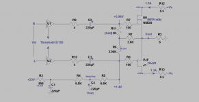
The best line amp I have to drive DEF is a Threshold S/150 power amp which I operated without its traditional loads of 4, 8 Ohms etc. The attached schematic shows the arrangement of this prototype. The stereo output signals from S/150 were ~summed to mono in DEF.
The music emanating from the 3-way boxed loudspeaker [ADS L730] was superb. It was detailed from top to bottom. The bass was tight and punchy, the vocals were life-like, and the highs sparkled.
The music of this amp through the full-range MCM musical instruments was also great. It was full-bodied in the bass region, the vocals were detailed, and the highs were crystal clear for this limited high-end of loudspeakers.
Attachments
In real life you want to carefully regulate the - supply, or any noise or
variation goes right to the output.
variation goes right to the output.

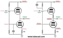
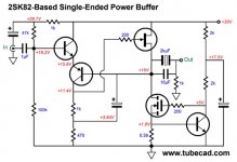
John Broskie write interesting solutions about noise eliminations techniques in his MOSSIT 2SK82 power buffer with Aikido mojo
Even More Single-Ended Amplifier Circuits
Even More Single-Ended Amplifier Circuits
Attachments

In real life you want to carefully regulate the - supply, or any noise or variation goes right to the output.
The main PSU is not regulated. I found sinusoidal signals at the output of both [NJF-MOS] and MOS-SIT DEFs. They were reduced in both cases to ~5 mV when Vin in the attached schematic was grounded or connected to a low output impedance signal source. I did not hear hum up close to the woofer. Please note that the +23V supply which drives the resistor string is not that driving DEF. It is separate because I pre-energize the string before I apply main DEF power to safeguard the FETs.
I'll take a closer look at the output noise for MOS-SIT DEF amp and report.
Attachments

John Broskie write interesting solutions about noise eliminations techniques in his MOSSIT 2SK82 power buffer with Aikido mojo
Even More Single-Ended Amplifier Circuits
Broskie used an exact level of inverted ripple to cancel ripple at the power output of his followers. He summed 2 ripple signals of equal amplitude and having 180 degrees out of phase. This is a smart solution. His circuits are not Pass DEFs.
Ripple in DEF output
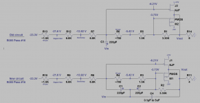
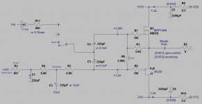
The attached schematic pertains to the DEF of 2SJ28 and IRFP140N. The following are the findings for ripple at the DEF's output at idle conditions.
1. The power rails for the FETs show numbers in square brackets. They were measured with an AC multimeter. They are the magnitude [in Volts] of ripple.
2. The ripple on both rails are similar in amplitude but are 180 degrees out of phase. They [mostly] cancel each other at the output of DEF to get an AC reading of [0.001] for residual ripple.
3. This residual ripple at the output of DEF shows up on the scope as ~5-10 mVp-p on the 20 mV scale.
4. Note the three-position switch at the joint of the two input capacitors [2x220uF]. It floats or is at the open position. The scope showed that residual ripple which was already seen at the output also appears at the joint of the input capacitors.
5. Bootstrapping via the 220uF or 15uF capacitors increased the magnitude of output ripple to [0.053]. The phase of this ripple was the same as the ripple on the negative power rail of DEF.
6. Ripple induced by bootstrapping was reduced to ~5-10 mVp-p by moving the switch to either ground position or to the output of the OpAmp.
7. The output of the OpAmp shows either a 680 series resistor or none. No effect on the magnitude of remnant ripple at the output. The 680 resistor gave a clear picture of the ripple on the scope. No resistor added fuzz to it.
8. Why a 680 resistor? Mr. Pass found this output impedance for the line amp [actually 600 Ohms] lowered distortion per his presentation at BAF 2016.
9. The other changes of components in the schematic [like the capacitors at the input] did not affect the magnitude of ripple.
I heard this ~5-10 mV ripple up [very] close to the woofer. Regulation of the negative is needed per the suggestion of Mr. Pass. The magnitude of the ripple on the rails during music conditions will not be equal so as to fully cancel at DEF's output as said in point #2. Mud is expected in the music.
Attachments
I really need to re-read/re-hear Papa's DEF fun from BAF ;
as I understood it first time , main goal is to combine two adequate parts from two reasons :
-maximally simple (non -existent in classical style) biasing circuit
-more than happy coincidental THD spectra , as result of two dissimilar transfer characteristic
so , before taking your (good ) work as effort in marrying two not-so-adequate parts (??) , I need to go back and grasp it one more time
especially bcs Papa threw me a bone , saying that DEF is same fun as my beloved M2
Thanks, Zen Mod. Your contributions will be appreciated. DEF may have exposed another "charm" property that birds which have "different feather" can flock together.


DEF may have exposed another "charm" property that birds which have "different feather" can flock together.
Perhaps accidentally true in this case. I have one driving my Tannoys,
and it is very pleasant.
Perhaps accidentally true in this case. I have one driving my Tannoys,
and it is very pleasant.
Great news. This cooperation of SIT and MOS gave a viable and a pleasant sounding DEF.
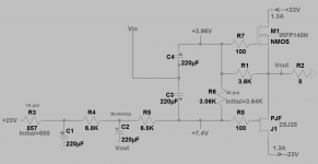
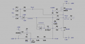
The schematic of the DEF power amp which I showed in Post#132 was modified to use overall negative feedback. The attached schematic shows this change.
1. OPA2134 dual OpAmp was used instead of LF356N mono OpAmp. It was given an asymmetric PSU of +19V/-12V.
2. OpAmp [U1] sums the L and R [Vin] inputs and its output drives directly IRFP140N.
3. A 15K resistor connects the power output of DEF [Vout] to the inverting input of the OpAmp, and thus enables overall negative feedback to do its thing.
4. U3 is the second OpAmp in OPA2134. It is a non-inverting buffer and drives directly 2SJ28 via a coupling capacitor.
5. The bottom left of the schematic shows the derivation of the +19V PSU rail from +23V.
6. Why an asymmetric PSU to the OpAmp? It is to accommodate 2SJ28. Suppose I use a +/-12V PSU for OpAmp. At a Vin music signal of 0V, the gate of 2SJ28 is at ~+7.5V. As the music signal; say 5Vpeak goes negative, the resultant ~+5 V positive signal at the gate of 2SJ28 rides on top of its fixed +7.5V. The sum of the fixed and the music signal voltages exceeds the +12V rail. Thus the gate of 2SJ28 is stuck at +12V, while its source can go even more positive than +12V. Thus, the gate of 2SJ28 loses control of its drain-source channel, and this can't be good. This consequence was sonically apparent unless a higher; say +19V rail was used. Note that the sum of +19V and /-12 V/ is 31V and is below the 36V Absolute Max Rating for OPA2134.
7. The PSU of the DEF stage is also an asymmetrical +28V/-23V for the same reasons as in point 6.
This integrated DEF amp sounds great from its brilliant crystal-clear highs to its tight snappy bass. Amazing lifelike vocals. It is thermally stable.
Attachments
In conclusion..
DEF by Mr. Pass is a power output stage. It is ingenious and simple. It is 2 FETs and 3 resistors to bias them. My prototypes per his teaching at BAF 2016 operated flawlessly and were stable thermally. The combination of an OpAmp line amplifier and DEF presented a pleasing and satisfying music. I'd venture to say that this combo has a characteristic music signature via the ADS L730 loudspeaker. The bass was clearly defined, and the mid/high ranges were brilliant and pinpoint. The vocals were up front and natural.
DEF operates in a push-pull device mode. Its output has ~ 0 V DC offset because its two FETs and their 3 biasing resistors operate as a novel DC servo. Thus it performs as good as or maybe better than a classical complementary push-pull pair. It can replace the latter or any power output stage [if blown] but with a circuit modification which was mostly understood experimentally. A possible integrated DEF amp maybe like that of SONY VFET..but simpler. No PSU regulation is needed and has a thermally stable self-zeroing bias circuit.
The VFETs 2SK82 and 2SJ28 are a pair of complementary symmetry devices for push-pull power outputs. Suppose a DIYer has 2SJ28 only and not its natural complement. Great news. DEF'it with a cheap and available N-channel MOSFET like IRFP140N. Thus this DEF methodology of Mr. Pass is broad in its scope of application to give great sounding amplifiers.
I can easily relate to the exuberance of Mr. Pass during his presentation of DEF at BAF 2016. DEF runs hot but is a cool design which can be readily embraced by audio DIYers.
Antoinel
I have enjoyed reading about your DEF experiments 😀
Your contributions are both enjoyable and clear.
I have some R085s and will be waiting for Nelson to post the teaser he mentioned - transformer front end with R085s/IRFxxx
Best and thanks
Bob
I have enjoyed reading about your DEF experiments 😀
Your contributions are both enjoyable and clear.
I have some R085s and will be waiting for Nelson to post the teaser he mentioned - transformer front end with R085s/IRFxxx
Best and thanks
Bob
Last edited:
- Home
- Amplifiers
- Pass Labs
- DEF Amp