Yes of course, parts wise it doesn't look too complicated.
If it fits the drivers.
Edit: Tried to cancel the order for Order the Dayton Audio XO2W-4.5K - SoundImports but it's already on the way.
Should I return it or would it be of use?
If it fits the drivers.
Edit: Tried to cancel the order for Order the Dayton Audio XO2W-4.5K - SoundImports but it's already on the way.
Should I return it or would it be of use?
Sorry for steering you towards those particular Dayton crossovers, it would be best to return them.
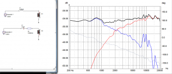
On the Q100 crossover, I can see a 3.9 uF capacitor. This would indicate that all you need to do to get the speaker working is to put a 3.9 uF film capacitor in series with the tweeter.
The Q100 specs state a crossover frequency of 2500 Hz.
Taking into acount the increase in impedance of the drivers at the crossover frequency, I would suggest you then add a 1.0 mH air core inductor in series with the bass/mid driver.
Monacor is cheaper than SoundImports for air coils. Check Monacor Europe (German Warehouse).
LSIP-100/1 - Air Coil - Monacor UK | Monacor UK
Last edited:

Wait, so I've checked the drivers now. See images.
I've only disassembled one speaker for now, and couldn't find any screws that would let me separate the driver.
Also, I'm not able to identify which of the pairs is the tweeter, can this be inferred by the resistance?
I've measured the resistance with a multimeter, across each pair.
The resistance of the multimeter terminals is 0.2 ohm.
The resistance of the driver wires is 3.3 ohm (at the label) and 3.1 ohm.
Can this be correct, or am I doing it wrong? 🙂
They go into a 4pin connector.
Attachments
Last edited:
You're getting a resistance of around 3 ohm which indicates a nominal impedance of 4 ohm.
Don't try to separate the drivers!
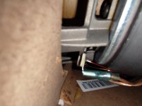
The tweeter connection appears to be the one on the right of your third photo, if that little black wire going into the top of the unit is anything to go by.
Don't try to separate the drivers!
The tweeter connection appears to be the one on the right of your third photo, if that little black wire going into the top of the unit is anything to go by.
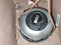
Do you realise that this is a coaxial driver? The tweeter is in the centre of the mid/bass speaker, not separate from it.Small speaker = tweeter
Big One = Woofer or full range
I also have a dead pair of these speakers and if I remember correctly, there are some
markings on the pcb where the 4 pin connector with the speaker wires goes. Hopefully
that will help you figure out which wires go with which driver.
markings on the pcb where the 4 pin connector with the speaker wires goes. Hopefully
that will help you figure out which wires go with which driver.
I meant to separate the whole driver combination from the chassis so I could better check which is which, but if it's not necessary, then it's fine.
They don't have a common wire, it's 4 wires with 2 ground wires marked black. What I meant is I cannot see which of the pairs goes to the tweeter and which one goes to the woofer.
I found the screws, they glued a cover to the front.
Thanks for the hint, there are indeed markings. Let me send an update, one sec.
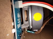
As a double check - the connection in your first photo appears to be going to the bass/mid driver section.
Combine that with my last observation and tell me if the two observations are compatible.
Combine that with my last observation and tell me if the two observations are compatible.
The meter or a coin cell can be used to see which speaker crackles when connected, helping find the wires, provided the speakers are separately connected without an internal crossover.
No, I did not look at any circuit diagrams.
No, I did not look at any circuit diagrams.
The tweeter connection appears to be the one on the right of your third photo, if that little black wire going into the top of the unit is anything to go by.
That seems correct.
On the third image:
Right side goes to HF+, AGND and has 3.3 ohm (minus 0.2 ohm of multimeter)
Left side goes to LMF+, AGND and has 3.1 ohm (minus 0.2 ohm of multimeter)
There is also another label reading Uni-Q 4 ohm
If necessary, I can separate the driver from the chassis

ok so if I get this right I need:
2x 3.9 uF film capacitor (which voltage?)
2x inductor is 0.68 mH (from here: SP-Spulen | Visaton)
Do I need to pay attention to specific types/or manufacturers?
And, I need to get some kind of terminal connectors for the new backpanel, I guess I can then just
solder the parts above to the pads of the terminals if everything is in line?
And, I guess I need to move the old blowhole/tube to the new panel then as well, at the same position.
Last edited:
50 V or greater for the capacitor.
There is a choice of Visaton 0.68 mH coils. Either will do, but the lower resistance one is preferable.
Don't forget the 0.68 ohm; 5W ceramic resistors!
And order terminal plates like the ones JMF showed you.
There is a choice of Visaton 0.68 mH coils. Either will do, but the lower resistance one is preferable.
Don't forget the 0.68 ohm; 5W ceramic resistors!
And order terminal plates like the ones JMF showed you.
Missed your edit!
Any film capacitor intended for loudspeaker crossover use will do - usually polypropylene types.
You can solder the parts directly to the terminal pads, but should fix them securely to the inside of your new back panel. The Visaton coils have a handy screw fixing and you could use hot glue for the capacitor and resistor.
And, yes, you need to relocate the port to the same position on your new back panel.
- Home
- General Interest
- Everything Else
- Dead KEF X300A - what to do with them?