Hello.
First time post so go easy on me. I picked up a NAD 3120 with the hope of using it as a tempory input selector/phono amp for my power amp (Nord NC500). After unlinking the preamp and power amp I did a quick DC voltage test on the preamp outs. I'm getting around 200mv on both sides. This doesn't sound normal to me and not something my power amp and speakers will be happy with. When testing the NAD as a power amp then I get a more normal reading on the speaker outputs. Using the internal trims I can get a reading of 0mv.
Is this normal behaviour for the NAD or does it sound like an issue?
Thanks in advance.
Electrodaddy

Welcome to diyAudio 🙂
Quick possible answer without seeing a circuit diagram... if the preamp output is AC coupled (it likely is) then yes, perfectly normal to see the voltage as you are reading leakage through an unterminated capacitor feed.
Adding a resistive load (say 100k) across the output should/would bring the DC voltage to zero.
OK, I've just pulled a diagram for this and yes, it is AC coupled but with added complication of series FET muting.
Based on what I see here then I would say that the output should be at near zero volts however I would urge you to add a resistive load as a test and make sure that the voltage is zero.
If you haven't a suitable resistor then couple the pre to the power amp in the normal way but do not switch on the power amp.
Now check there is zero volts at the power amp input when just the preamp is on.
Attachments

Thanks for the info. Initially, I had no reason to think there was a fault so I did temporarily connect the preamp outputs to my amp and my woofers popped right out. This is what led me to believe there was a DC offset problem which was being amplified. However, perhaps my power amp doesn't cater for unterminated capacitances shoved in it.
Do the test I outline above and be sure. Looking at the diagram (above) there should ideally be no voltage present at the output.
There should always be zero voltage at the 560 ohm series resistor because the design actually includes a 'pull down resistor' which is the 100k.
So there should never be DC voltage at that point. You need to confirm that.
The FET could conceivably pass a small gate current when on but again, studying the diagram I see there is the balance control arrangement which should pull the voltage back down to zero.
Just a thought... you are using the correct preamp output sockets ? and not accidently measuring the voltage on the NAD power amp input half of the socket pair.
Thanks again for the help again. I'm definitely testing the preamp outputs. I tested again with the power amp connected but turned off. I got 101mv Left and 107mv right.
Do the test I outline above and be sure. Looking at the diagram (above) there should ideally be no voltage present at the output.
There should always be zero voltage at the 560 ohm series resistor because the design actually includes a 'pull down resistor' which is the 100k.
So there should never be DC voltage at that point. You need to confirm that.
The FET could conceivably pass a small gate current when on but again, studying the diagram I see there is the balance control arrangement which should pull the voltage back down to zero.
Just a thought... you are using the correct preamp output sockets ? and not accidently measuring the voltage on the NAD power amp input half of the socket pair.
The output is already AC coupled but as you point out, the muting FETs complicate things a bit. If it were mine and the DC was bothering me, I'd replace the FETs with reed relays which would cause absolutely no DC shifts. A 2N7000 mosfet is an excellent relay driver as it requires no resistors on the input to be driven from 5V logic.
G²
Something is definitely amiss with that result.
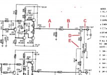
Measure and record the voltage at these points and lets see what is going on. Connect the black lead of the meter to the preamp ground (usually chassis ground) and measure and record the voltages at these 5 points.
All points apart from D and E should be zero.
Point D should 'rise' to around zero volts when unmuted (normal operation) and should fall to around minus 5 volts give or take when muted. In other words there should be little to no positive voltage on points D and E.
I'll look in later 🙂
Attachments
Also...
Has anyone previously replaced or linked out the coupling caps in the preamp output in some 'attempt' to improve things ?
If they have been linked out then you would pass the true DC offset of the output circuit directly to the pre-out sockets.
Has anyone previously replaced or linked out the coupling caps in the preamp output in some 'attempt' to improve things ?
If they have been linked out then you would pass the true DC offset of the output circuit directly to the pre-out sockets.
Here are the results. Something certainly amiss....
A: 111mv
B: 111mv
C: 112mv
D: 19.7v
E: 625mv
A: 111mv
B: 111mv
C: 112mv
D: 19.7v
E: 625mv
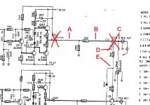
Interesting. Points A and B being the same suggest no current flow through the 560 ohm.
The problem has to be those caps. See if anyone has shorted them out under the board.
If not then take the caps out and repeat the test. There should now be zero volts on the 560 ohm.
The problem has to be those caps. See if anyone has shorted them out under the board.
If not then take the caps out and repeat the test. There should now be zero volts on the 560 ohm.
Ok, so they weren't shorted out and I've now removed them So here are the new results...
A: 88mv
B: 88mv
C: 88mv
D:19.8v
E: 598mv
A: 88mv
B: 88mv
C: 88mv
D:19.8v
E: 598mv
The plot thickens 🙂 and this is really an odd one, however......
With the cap removed, the only possible point that can feed voltage onto the output line is the FET. The problem with that is the FET has a 10 Meg ohm resistor supplying it with voltage, and that means in simple terms that 10 Meg couldn't superimpose such a high voltage onto that line.
But we need to prove this once and for all.
If you look at the circuit you will see that removing the FET isolates both the final output line and the line with the 560 ohm.
So if you remove Q509 then points A, B and C are all then tied to ground via the 100k and balance control. In other words no voltage can possibly then appear at those points.
Perhaps before doing any more unsoldering, and based on the evidence so far it would be worth you checking that the ground end of the 100k really does have no voltage present and also that the two connections on the balance control shown as going to ground also have no voltage present.
A floating ground could conceivably cause this problem so that is worth checking. Measure directly on the leads of the resistor and pins of the control if possible to prove.
Does that make sense ? I can't honestly see it being related to the FET simply because 600mv via a 10Meg can not create the 88mv you are seeing (effectively) across the 100k.
Thanks for all your help so far. I really appreciate it. Just to clarify....You mention a balance control? This amp doesn't have one. Unless I've completely misunderstood?
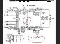
I'm looking at a combined service manual for the two products. Reading a bit closer and I can see it shows on the block diagram that the balance control is not fitted on the 3120.
So my mistake on that. All the rest of the basic circuitry should be the same though, and the above items to test are still valid.
It is an odd problem because by lifting the cap you have isolated the output line from anything with voltage present, the 10Meg resistor excepted.
Another unusual cause could be leakage on the print, typically from contamination such as a leaked capacitor or spillage of some kind.
Its really a case of isolating that output line now to see where the voltage is coming from.
Attachments

Ok great. So cap and FET removed. So yes, indeed there is no voltage at those points. Eagerly awaiting the next step!
- Status
- Not open for further replies.
- Home
- Amplifiers
- Solid State
- DC offset on NAD 3120 preamp output