Ideally you should measure no DC across the bridge. If you do, and if its below around 1.3 volts dc then the device is stopping that DC passing to the transformer. If its 1.3v or slightly more then it means there is more DC present than the filter can stop (unlikely).
I measure right now playing it low volume playing music....
i see no DC voltage just 00.00 on the multimeter....
Do i need this filter? being 00.00v on DC?
Think i can live without it? Or since it's made i can leave conected to the mains to the speaker and forget about it?
You probably don't need it tbh. DC on the mains seems to affect large toroidal transformers mainly. If you regularly see no DC across the caps then its not really needed.
This explains it all in detail,
Mains DC and Transformers
This explains it all in detail,
Mains DC and Transformers
Sure, no argument if that PVC box is in free air, it's as safe as any domestic wiring but I was actually concerned with the speaker box. I've been shown (couldn't economically repair) a couple of pairs of these popular, inexpensive, powered monitors and they were burned out internally. Luckily, no one was injured, but it seemed to me that plastic material, either damping or wrapping had sagged onto the hot electronics and eventually caused ignition. - Don't like 'em much after that. 🙁The box is safe enough if its all plastic.
Ah, you mean the whole caboodle. It does sound a bit of a hazard from what you say. I've never seen or seen in one tbh
Sure, no argument if that PVC box is in free air, it's as safe as any domestic wiring but I was actually concerned with the speaker box. I've been shown (couldn't economically repair) a couple of pairs of these popular, inexpensive, powered monitors and they were burned out internally. Luckily, no one was injured, but it seemed to me that plastic material, either damping or wrapping had sagged onto the hot electronics and eventually caused ignition. - Don't like 'em much after that. 🙁
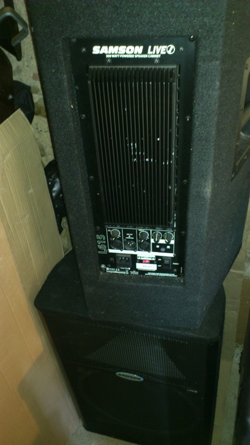
Samson is not exactly inexpensive.... 🙂 a lot of pro's use their stuff!
Compared to Mackie they are half the price, but the sound is good enough for me as the power they have.
When i play loud music, i mean Gig loud music on my house after 30minutes i always go check the cooler of the back of the speaker and it's barely warm.... i have that concern about it! 🙂
Now with the varnish on the transformers i will be super atented to that even more.... let's see... Hummm is still present but not that loud to concern... still a problem but i think my wife now can live whit it... and if "they" are happy it sure is down a lot! 🙂
Next stage will be the mu-metal or ultraperm around the transformer...
does anyone know if i can just glue the ultraperm foil to the transformer? Or should build a case of plastic around the transformer wrapeed then with the ultraperm or mu-metal foil?
Another concern... is wrapping the speaker box were the board sits with a material that will not get magnettization from the woofer to the electrics? Should i do that to? Or not needed for noise rejection and hum concerns...? maybe alluminum tape? is alluminum tape condutctive?
Last edited:
Hi guys,
I have some questions regarding the DC-Filter, which I built from this site:
DC-Blocker - Scintilla-buizenversterkers
http://sound.westhost.com/articles/xfmr-dc.htm
Some of the filters use some capacitors in series, but some use the +-poles, some the --poles connected together, some of capacitors are connected between + and -. What is the right way to connect the capacitors in series?
Another question:
How to measure the AC's DC in the right way? When I measure between L and N, my meters jump between 2 and 30mV.
Many thanks,
Stammheim
Hi guys,
I have some questions regarding the DC-Filter ............
Some of the filters use some capacitors in series, but some use the +-poles, some the --poles connected together, some of capacitors are connected between + and -. What is the right way to connect the capacitors in series?
Another question:
How to measure the AC's DC in the right way? When I measure between L and N, my meters jump between 2 and 30mV.
Many thanks,
Stammheim
The filter design paper you have used - http://sound.westhost.com/articles/xfmr-dc.htm - explains it all correctly
Last edited:
"How to measure the AC's DC in the right way?"
With a large resistor feeding a small integrator cap, 100K and maybe 10µF.
With a large resistor feeding a small integrator cap, 100K and maybe 10µF.
Stamm,
I cannot see any advantage in using series connected capacitors facing in the same polarity.
Having series capacitors with opposite polarity can have an advantage if one believes there is significant leakage in the reverse direction when the voltage peak across the capacitor approaches 0.5Vpk. The forward facing capacitor limits the leakage current.
A parallel pair of opposite polarity seems to have even less going for it.
If you accept there is reverse leakage, then the opposite polarity capacitor offers no protection. The leaking capacitors just carries on leaking.
That website seems to be offering a solution that has nothing good about it.
Pity I can't read it, there maybe a clue to why he/she chose to do it their way.
Last edited:
Pity I can't read it, there maybe a clue to why he/she chose to do it their way.
Just swipe the text and copy and paste it into an online translator (Bing or Google) if you haven't the accelerators installed to do it from your browser.
Attachments
Translation is poor but it does not confirm why they chose that weird arrangement for the capacitors.
No clue to why the MUR diodes were chosen, since they are OFF in all normal operating conditions. There is no switching !
No clue to why the MUR diodes were chosen, since they are OFF in all normal operating conditions. There is no switching !
agreed. smells like "marketing" to me!
mlloyd1
mlloyd1
...
No clue to why the MUR diodes were chosen, since they are OFF in all normal operating conditions. There is no switching !
Are there any news concerning commercial available DC blocker components against buzzing toroidal transformers ?
I note still, that there are several so called high end (not cheap) audio power amplifiers on the marked with very loud transformers made in India
I note still, that there are several so called high end (not cheap) audio power amplifiers on the marked with very loud transformers made in India
You have current through the diodes during high power outtakes but it depends also how big the caps are. If you ask me, regular rectifier diodes will do.Translation is poor but it does not confirm why they chose that weird arrangement for the capacitors.
No clue to why the MUR diodes were chosen, since they are OFF in all normal operating conditions. There is no switching !
Yes, during start up and during abuse.You have current through the diodes during high power outtakes.............
But probably better not to conduct when the amplifier is in normal operation.
My condition is that they must not conduct during all normal operation for all valid audio signals into all valid audio loads.
Same rule as for output limiting allowing signals to pass.
Last edited:
My condition is that the filter must do its job the time when it's quiet in the room. The purpose is to reduce mechanical hum which you won't hear if you play loud.
Emotiva CMX-2 Line conditioner and DC offset filter.
http://www.amazon.com/Emotiva-CMX-2-Precision-Restoration-Common/dp/B008O37LXY
The CMX-2 precision AC line restoration and common mode filter system offers a solution to a less-familiar, common problem - DC offset on the AC power line. DC offset is usually the result of unbalanced loads or by flaws in the power distribution system itself. It can cause DC current flow in the transformers that power your audio equipment, making them run hotter, produce more mechanical hum, and, in extreme cases, even potentially causing permanent damage. In addition to removing line noise, the CMX-2 also totally eliminates this annoying and potentially damaging problem as well. The CMX-2 delivers clean power, free of high-frequency line noise and potentially audible DC offsets to your audio components. It also continuously monitors your AC power line wiring integrity and alerts you to common fault conditions like open grounds and reversed lines. It utilizes our exclusive Power Direct Connect mounting system, which connects the commercial grade outlet directly to the high current circuit board by the shortest possible path, eliminating power robbing resistive losses and other problems caused by less reliable and robust wiring techniques. The CMX-2 also uses top grade common mode and differential mode L-C filtering to reduce or eliminate all types of high-frequency noise. Can be mounted vertically or horizontally.
thanks, djk.
interesting ...
with just a very quick eyeball: 2 bridge rects and it looks like relatively "small" electrolytics are used for the actual dc blocking: 470u/16v.
for us with elderly eyeballs that need some help, a bigger internal pic available here: https://emotiva.com/products/accessories/cmx-2
mlloyd1
- Home
- Amplifiers
- Solid State
- DC filter